Large Scale Central

Yet another Skonkworks ugly duckling

A few more:

I haven’t spoken to my wife in years. I didn’t want to interrupt her.

My wife made me join a bridge club. I jump off next Tuesday.

My wife isn’t very bright. The other day she was at the store, and just as she was heading for our car, someone stole it! I said, “Did you see the guy that did it?” She said, “No, but I got the license plate.”

My marriage is on the rocks again. Yeah, my wife just broke up with her boyfriend.

Hi Mik:

Can the rear axle be removed from the power block to build an 0-4-4T loco?

Norman

Norman, if I used one of those lines with my wife she’d wire the layout to 110 and tell me to go touch the rails!

Norman Bourgault said:
Hi Mik:

Can the rear axle be removed from the power block to build an 0-4-4T loco?

Norman


The motor drives the rear axle. It’d be easier to remove the front one

OK, some update pix… Upper cab started using one of the resin windows I got off Dave Ottney cut in half.

(http://i1082.photobucket.com/albums/j371/AlleghenyValley/2012/P2020001_01.jpg)

I think it looks pretty darn good for a camel (they’z ugly, smelly beasts, lol!)

(http://i1082.photobucket.com/albums/j371/AlleghenyValley/2012/P2040002.jpg)

That low firedoor give me a backache just looking at it

(http://i1082.photobucket.com/albums/j371/AlleghenyValley/2012/P2040003.jpg)

Cab interior started. I gotta get all the controls and stuff installed before I can do the end walls, my fat fumble fingers barely fit now! Walking surfaces on real early stuff was usually painted with a non-slip pale yellow or light grey. The ‘sunflower’ I usually use was dried up, so I found it rather amusing to use ‘camel’ instead

(http://i1082.photobucket.com/albums/j371/AlleghenyValley/2012/P2040004.jpg)

I could use some advice… If you look closely at this pic, you’ll notice that the headlight is mounted off-center, actually beside the funnel instead of the usual location

(http://i1082.photobucket.com/albums/j371/AlleghenyValley/Winans171-1.jpg)

It’s a cool variation, but how would you model it so it looks prototypical, but is still strong enough to withstand the real world bashing it will probably get (especially during a roll-over derailment!)

Great job Mik! As for the headlight, Accucraft’s Mich-Cal shay #2 has a similar headlight configuration. it is mounted a little higher than on the camelback, but could be mounted similar. In one of your photos i see a hole (for a handrail im gessin) just below the stack on the smokebox, i would probable make or modify a headlight base that could be atached there with a screw or glue a piece of rod into the hole and then atach the base to the rod. just my 2c worth. looking forward to the finished result!

Mini update! Front cab wall went in the lazy way. I cut a bit of cd jewel case to fit the hole, then glued coffee stirrers and basswood to look like doors… I think I want at least one back door open, so it will be more work.

(http://i1082.photobucket.com/albums/j371/AlleghenyValley/2012/P2060029.jpg)

After studying the Hayes Camel restoration pics, I felt confident enough to finish the controls. Mr. Mogul dude will do for an engineer. I also burned a bit over half an hour drilling holes with a pin vice and sticking HO track nails in them to look like firebox stays since otherwise it was a great big boring

(http://i1082.photobucket.com/albums/j371/AlleghenyValley/2012/P2070031.jpg)

Headlight in the offset position installed and wired. The LED is a high intensity white, so it’s rather too harsh for a kero - but it was here, and I really didn’t like the color of the yellow one I had.

(http://i1082.photobucket.com/albums/j371/AlleghenyValley/2012/P2070030.jpg)

Now listen here, and I’ll tell you how to make you wife happy.
Ifin she says she wants a new washer for her Berfday ten by golly you’d better be gitten her a new washer.
I wasn’t married for over 43 happy years to the same women by not listening to what she was saying.
besides a washers much better help to her than goin out, U go out’n that’s it, but she’ll use dat washer evenry week.
PS. Love the music on you AV vid

Years ago, my dad had a bumper sticker (He got it at Strasburg, I think) that said “Steam Locomotives have a tender behind”… well, this one has a serious case of “ghetto booty”.

(http://i1082.photobucket.com/albums/j371/AlleghenyValley/2012/P2080001.jpg)

It’s probably the last free Delton shell around (the fleabay guy is OUT - has been since I got this one from him 4 or 5 months ago ), so I’m loathe to whack a section out… especially since there’s always a chance of really screwing up… but I’m not sure a tender should be longer than the locomotive, either. Anybody know how long a LGB Mogul tender is?

Mik;

Perhaps you could find a tender from a junked Lionel Hogwarts battery set. Those GWR Ry tenders are short, but probably could still be rebuilt with two trucks (short, chunky trucks like New Blight’s).

It’s a long shot, but it could work.

Best,
David Meashey

How about just scratchbuilding a tender for it? basically just a tank with a coal pocket on a flatcat…only hast to have a coupler at one end too!

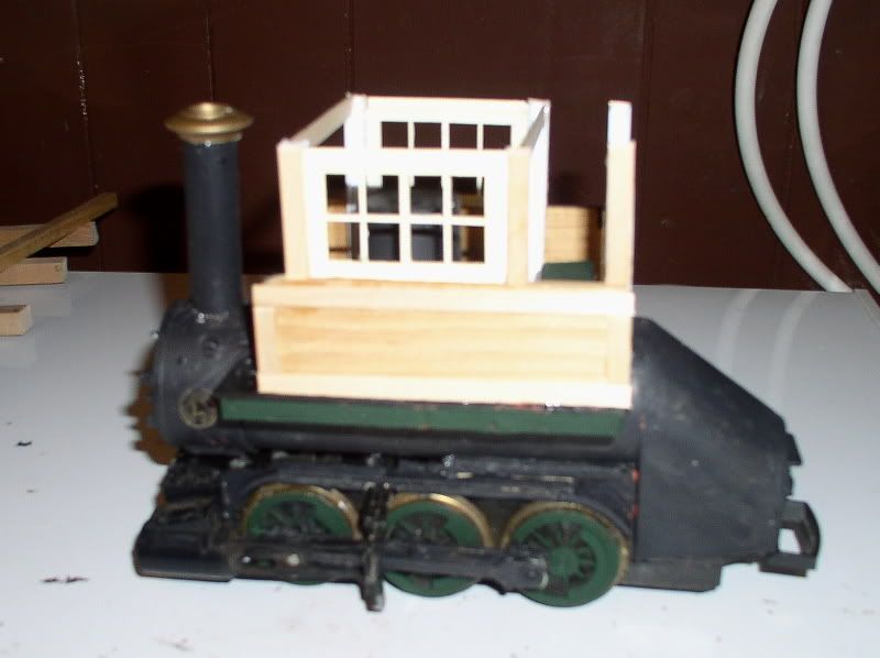
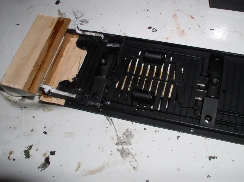
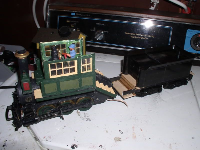
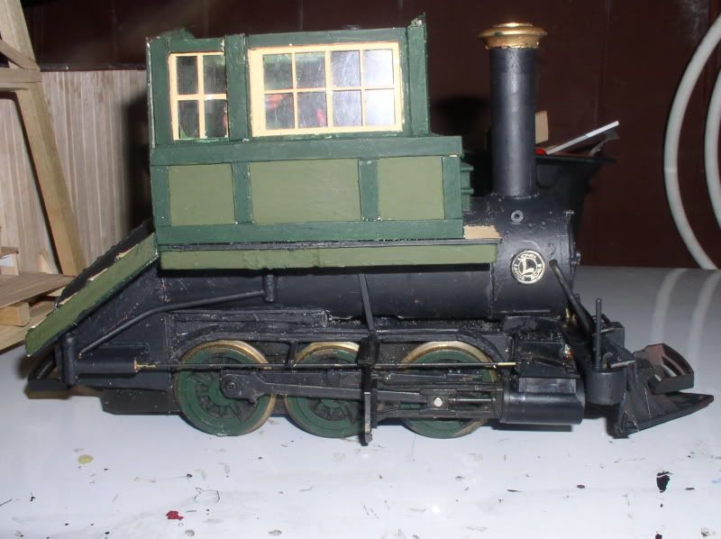
Well, after dithering for about 12 hours, I decided to bite the bullet and butcher the tender. The B’mann frame could only get just under 3/4" removed. The flanges just barely touch on r-1 curves now… and yes, those air tanks needed to go next. Both to clear the new wheel location and because there were no such thing as air brakes in the 1860s!

(http://i1082.photobucket.com/albums/j371/AlleghenyValley/2012/P2080001_01.jpg)

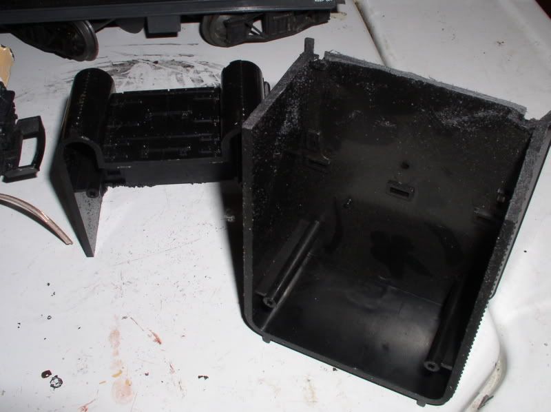
Oh, the huge manatee!!! Such a shame, but about 1-3/16" simply hadda go…

(http://i1082.photobucket.com/albums/j371/AlleghenyValley/2012/P2080002.jpg)

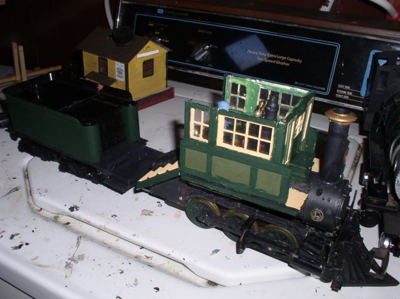
Splicing back together… I will have to file a vee joint and then putty to hide the seam better…

(http://i1082.photobucket.com/albums/j371/AlleghenyValley/2012/P2080004.jpg)
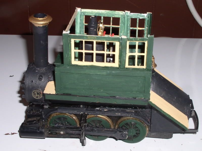
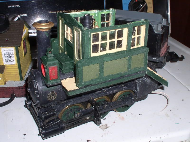
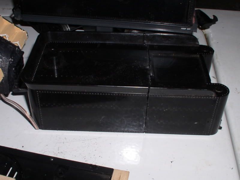
A bit better now

(http://i1082.photobucket.com/albums/j371/AlleghenyValley/2012/P2080005.jpg)

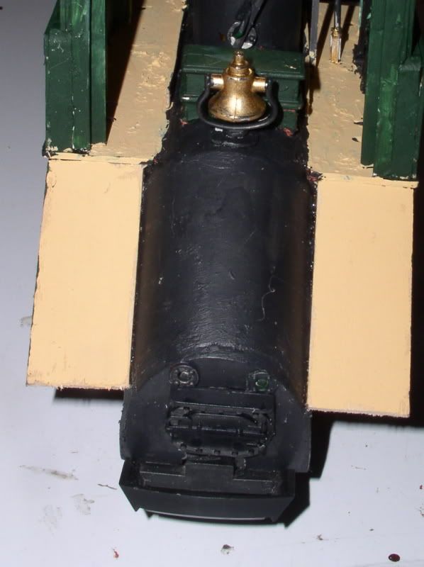
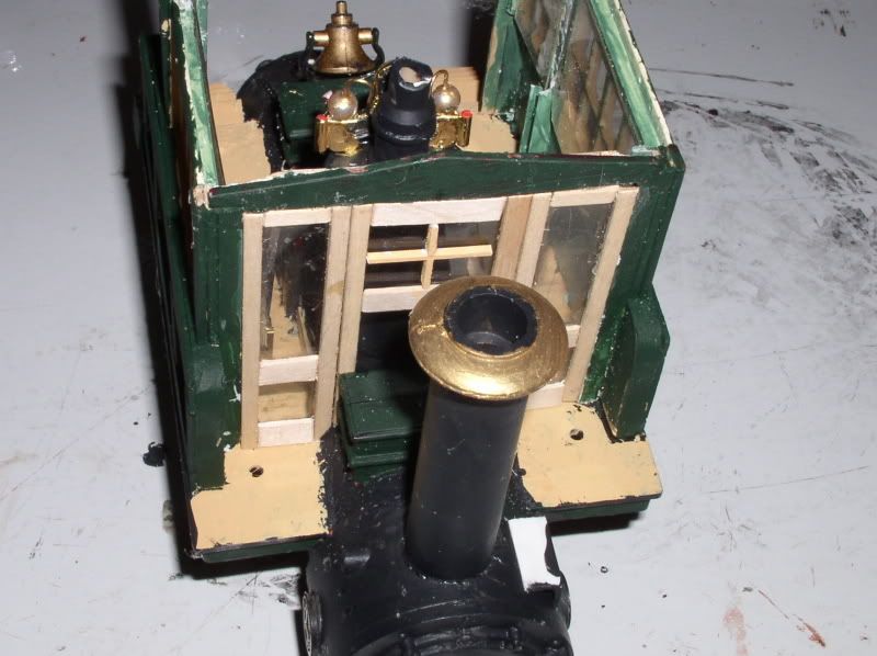
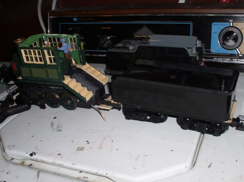
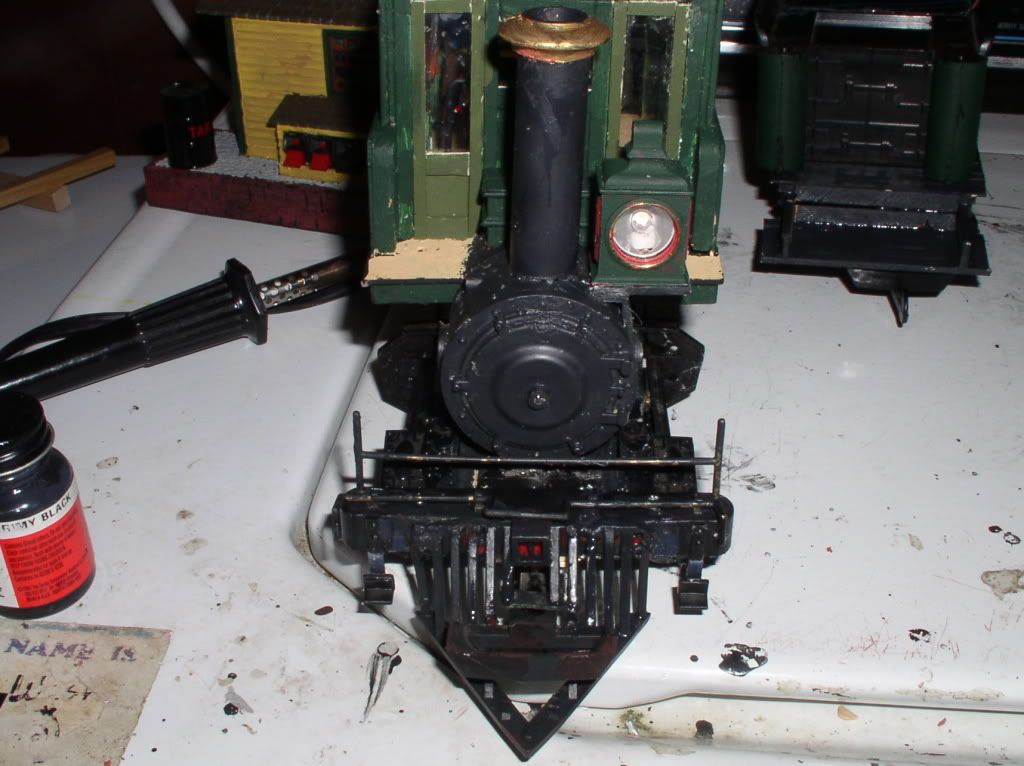
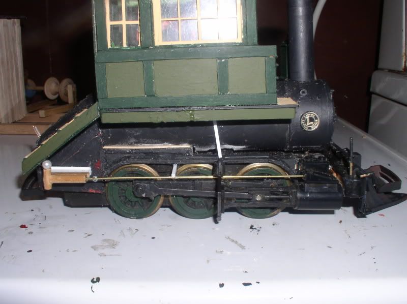
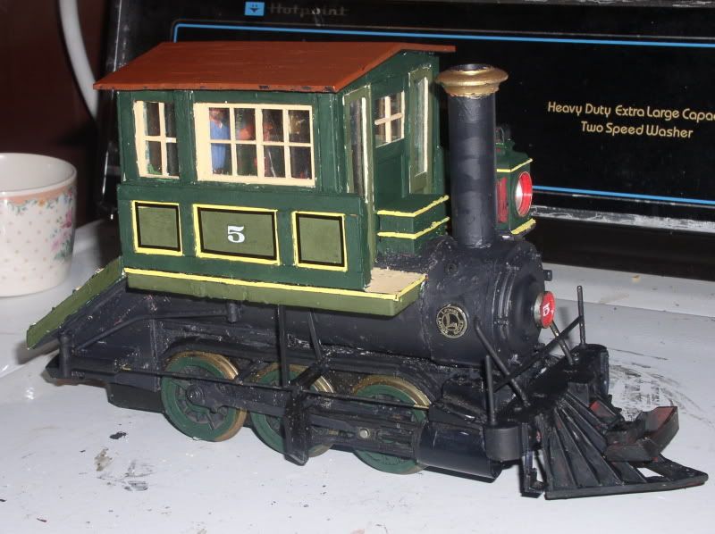
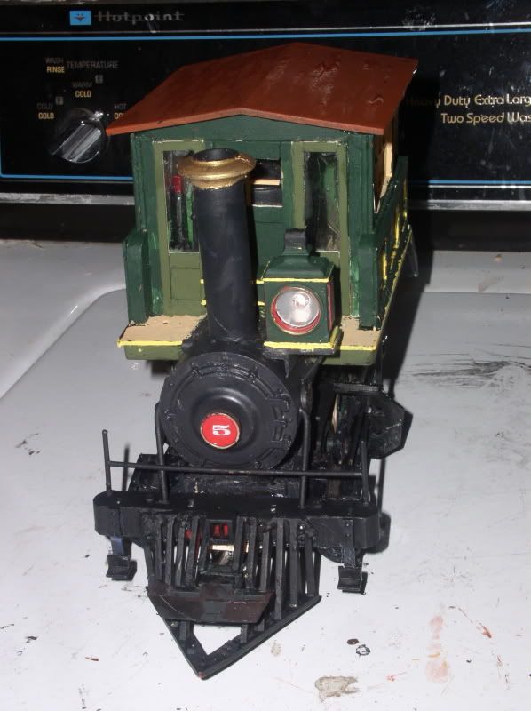
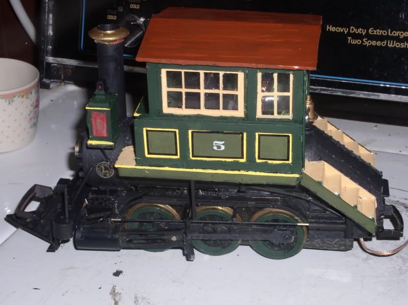
While the glue was drying I decided to attack the pilot. I usually dislike wooden (cowcatcher) pilots, mostly because they’re so overdone to the point of almost a cliche`… but this thing begged for one. Except I wanted a front coupler too. A bit of further butchery on the broken Lionel one that came with the chassis resulted in this.

(http://i1082.photobucket.com/albums/j371/AlleghenyValley/2012/P2090011.jpg)

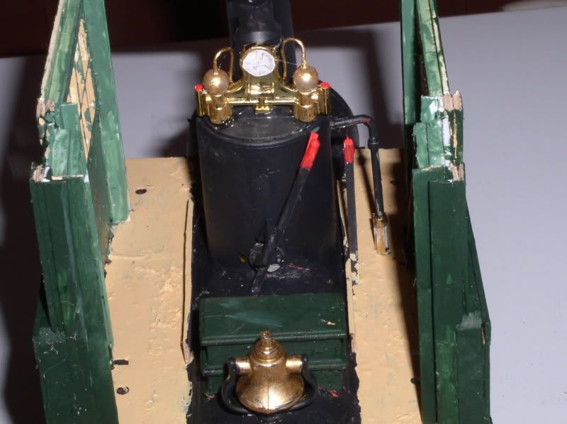
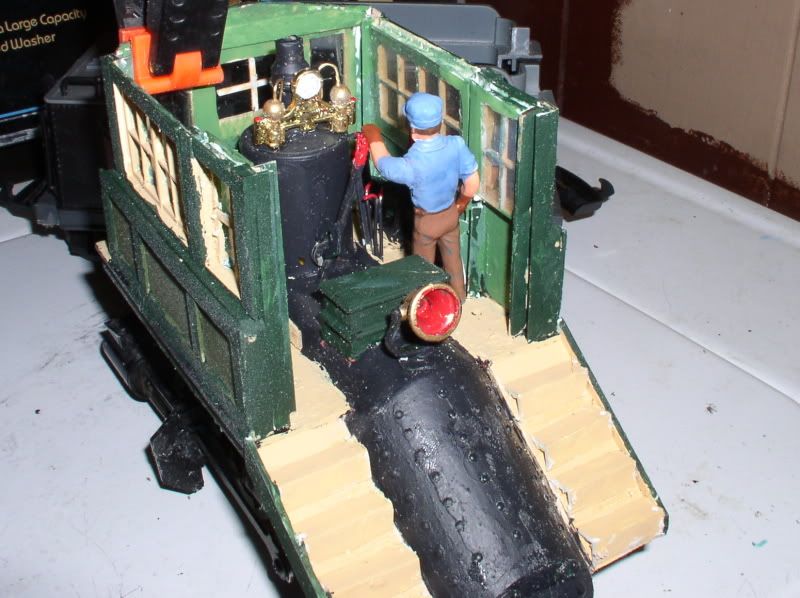
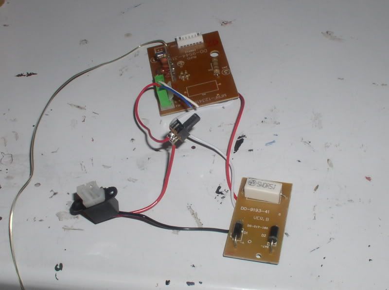
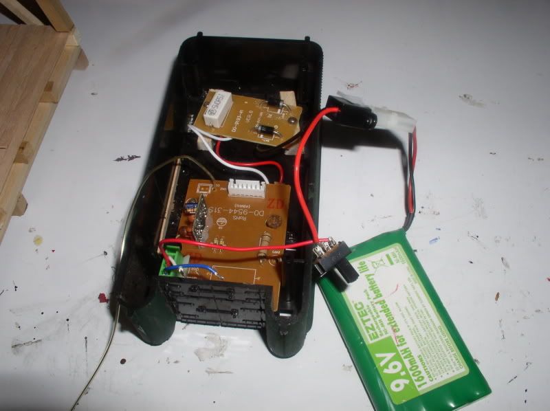
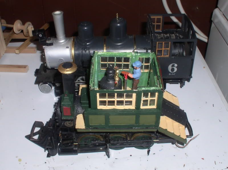
It’s… getting there. The big thing really holding up the show is the r/c truck (radio donor) that seems to be lost in the mail. Since I need to see how much space I’ll need for the circuit board(s) and antenna

(http://i1082.photobucket.com/albums/j371/AlleghenyValley/2012/P2090012.jpg)

Truck arrived today… in a honking HUGE box… turns out my $2 (plus shipping) donor was the size of an old fashioned Tonka Dump! Anyhoo, Removing the radio bits wasn’t all that hard… except for 1 screw that was behind stuff

(http://i1082.photobucket.com/albums/j371/AlleghenyValley/2012/P2100001.jpg)

Installed in the tender - yes the stand-off bits are drunk, no I don’t care … nobody will see them after it’s assembled! - Yet to do is wire a better main toggle switch and a charging circuit, and figure out which way it thinks is forward.

(http://i1082.photobucket.com/albums/j371/AlleghenyValley/2012/P2100002.jpg)

Now it’s stupid questions time! First, what would the best (and/or cheapest) way be to step down the voltage if I need to? The radio set-up is 9.6v, and I think the loco should amble which probably means 6v or less. Since it has to be on the output side (between the radio and motor) wouldn’t the usual diodes require doing it twice? I realize a resistor or pot wastes power and shortens run time, so what other options are there? Second, since I know jack about r/c, is the antenna, can I just loop it inside the tender shell? Or put it coiled under a coal load? Or do I need to solder up some brass handrails or other somesuch? Thanks in advance!

Hi Mik:

There is that guy on the other site who is always pointing out the problems with the Aristo Craft products. He definitely could help you.

The metal wheels running on the metal rails produce electrical noise as metal rubs on metal.

Try not to loop the antenna into a coil. Try to run the antenna around the interior perimeter of the tender body close to the lid away from the bottom of the tender and away from the electrical noise of the metal wheels running on the metal track.

Stepping down the voltage is cheapest with a voltage divider network using a pot with one end of the pot connected to the battery postive output, the centre wiper of the pot connected to the positive input of the motor and finally the other end of the pot and the negative output of the motor connected to the battery ground.

Norman

Norman Bourgault said:
Hi Mik:

There is that guy on the other site who is always pointing out the problems with the Aristo Craft products. He definitely could help you.

The metal wheels running on the metal rails produce electrical noise as metal rubs on metal.

Try not to loop the antenna into a coil. Try to run the antenna around the interior perimeter of the tender body close to the lid away from the bottom of the tender and away from the electrical noise of the metal wheels running on the metal track.

Stepping down the voltage is cheapest with a voltage divider network using a pot with one end of the pot connected to the battery postive output, the centre wiper of the pot connected to the positive input of the motor and finally the other end of the pot and the negative output of the motor connected to the battery ground.

Norman


What Guy. ?

Norman, the tender wheels are plastic. I’m outta metal ones at the mo. But thanks!

And I already talked to Greg a while back… I THINK he suggested a bridge plus 3 or 4 diodes in series across the middle… I saved parts of the chat in an email to myself, but darned if I can find it! (and would hate to buy the wrong stuff!)

The motor connections in this (Scientific/Eztec thing) are the blue and white wires on the larger board. I don’t think I can monkey with the input voltage without causing the radio to go all wonky or I’d just substitute a 7.2v battery to start with… unless the separate board is something that just drops voltage anyway? As I said, I know bugger all about r/c, that’s why I’m trying to (mostly) do a simple chop & drop from the truck - which doesn’t look to have much in the way of variable speed

The injector wasn’t invented until 1858, and took a while to catch on. So early locomotives had feedwater pumps to put makeup water in the boiler while underway. Some were driven by the cylinder crosshead, or a separate crank throw, or an eccentric on the axle … Ross Winans put them on an extension of the valve rod on the early Camels.

(http://i1082.photobucket.com/albums/j371/AlleghenyValley/uss1.jpg)

I thought, well, that’s kinda cool… so I made up some pumps out of dowel and plastic pearls

(http://i1082.photobucket.com/albums/j371/AlleghenyValley/2012/P2120011.jpg)

This might actually work!

(http://i1082.photobucket.com/albums/j371/AlleghenyValley/2012/P2130001.jpg)

piped and painted

(http://i1082.photobucket.com/albums/j371/AlleghenyValley/2012/P2130001_01.jpg)

I know this isn’t the greatest angle, but just to give new folks an idea how tiny this thing is - Here it is with the LGB Mogul I’m trying to assemble from parts. The top of the Camel boiler is just above running board height on the mogul…

(http://i1082.photobucket.com/albums/j371/AlleghenyValley/2012/P2130003.jpg)

It’s short for short trains! Really neat.

I got a little detailing done today so I thought I’d share the pix…

(http://i1082.photobucket.com/albums/j371/AlleghenyValley/2012/P2160001.jpg)

(http://i1082.photobucket.com/albums/j371/AlleghenyValley/2012/P2160003.jpg)

(http://i1082.photobucket.com/albums/j371/AlleghenyValley/2012/P2160005.jpg)

I’ll probably either solder the connector jack, or bend the railings yet, before calling it a day