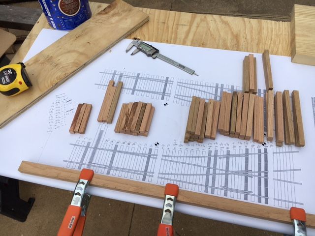
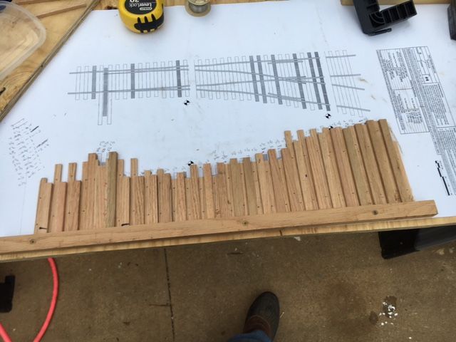
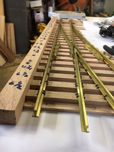
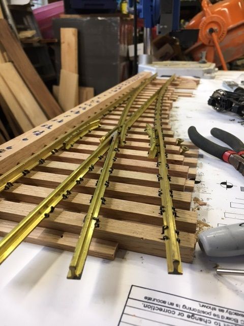
Not sure how it happened, but somehow, I have managed to build a #4 turnout. It has taken me about 24 total hours but its done and to my surprise it actually works. Well sort of. I still have to add the throw bar. Haven’t settled on exactly how I want to handle that. I’ll get that figured out this week. But I have run several different pieces of rolling stock through it with no derailments in either direction. It looks like a bulls a… tied up with a barbed wire fence but heck its my first one. They will get better. Anyway, I started by cutting the ties out of oak (first mistake) and then making a jig to hold the ties during construction. Oh, BTW, I am not using any type of backer board or splines. The tie jig as shown below worked well until I started driving spikes and then the ties wanted to slide out the side that’s not confined.
Ties
Jig
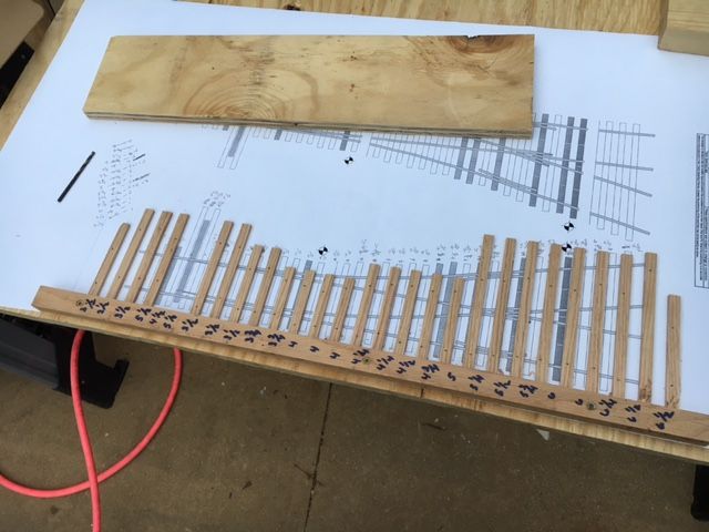
Ties in Jig
Unfortunately, due to many frustrations throughout this brutal process, I did not take any intermediate photos, sorry. Now that I am confident I can do this and have figured out most of my mistakes, I’ll do a better job of documenting the entire process on the next one. So here it is. Questions, comments and criticisms welcome. Just remember, its my first one, so be easy.
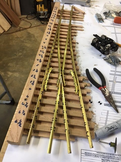
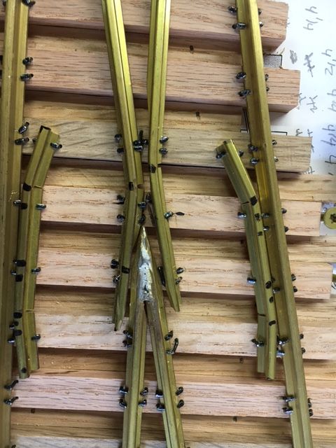
I’m tired of driving spikes  I think there are like 264 spikes in that one turnout. Not to mention the untold number that I had to pull because I bent them trying to drive them into oak. I finally started predrilling each one and that made life much better. Just think, I only have about … never mind… I don’t want to think how many I have left to build. Just take’em one at a time Dan!!!