Large Scale Central

USA Trains Switch Issue with Locomotive Drivers

LSC Friends: I did not an answer to this question on an existing discussion thread, so i am starting this new thread for your input. finally closed the mainline loop of my g scale backyard layout using USA solid brass track and switches. The first locomotive I am using is a Bachmann Spectrum 2-6-0 Mogul on battery power. The locomotive runs great on the track including curves from 8’ to 20’ diameter. However, here is my dilemma. Most of the switches I purchased to use on this layout plan are 8’ diameter USA Trains solid brass rail switches. I noticed right away on the very first run that I had to hit these switches at half throttle or more to get the locomotive to not stall on the straight path of the switches. But then when I tried to run the locomotive through the divergent path of a switch onto the passing siding, forget it - the locomotive got completely hung up and caught in the switch. I did try tinkering on one switch by prying open the space between the guide rails and main rails as well as the frog, which helped somewhat. But I was afraid to do too much and damage this expensive switch. All of the cars go through the switch just fine, but the locomotive will not make it. I do have a #6 switch on the layout, and the loco made it through both paths of this switch at half throttle or better, but still wanted to stick somewhat.

So my question is this - has anyone encountered this issue with the USA 8’ diameter switches, and what did you do to fix the problem. Can the spacing between the guide and main rails be readily ground out, forced apart or some other fix to permit my locomotive to run through freely, or should I scrap the idea of using 8’ diameter switches and go to #6’s?

Any thoughts, advice and recommendations relative to this problem is appreciated!

Mark
updated to address battery power I missed:

First, I have found that I run screaming from any switch that has a “radius” less than 5 foot. I have not used the USAT 4’ radius switches. While most locomotives made will negotiate an 8’ diameter circle, assuming that the same locomotives will negotiate a 8’ diameter switch is a mistake.

First, I do want to clarify a few things, in one sentence you say the loco stalls on the straight side, that is very strange, it would have to be something catching on something physical, it could be tight gauge, but sounds more like you hare hitting the frog. It would help to identify the direction you are travelling in the switch.

Now, the next thing is derailment issues. The first thing you do is check the gauge of your locomotive wheels, all of them pilot, drivers, tender. The next thing is to check the gauge of the switch.

Now you are going to have an issue, what specification to use for these measurements. This is a complex subject since virtually nothing made by USA Trains, Aristo, or LGB meets the standards. They have played with the specifications to make something that usually works, but allows for greater manufacturing tolerances. I can completely explain this, but it is long and tedious.

You can look up the NMRA standards for large scale (and find 3 specs) and try to follow the “deep flanges” spec… that is the closest to what you already have.

To answer a specific question, narrowing the spacing between the guide and main rails (called the guard rail flangeway width) should NOT be done alone, you must make sure all your wheels are in gauge.

My bottom line is go all #6, or nothing less than the Aristo “wide radius” which is closer to a 10 foot diameter.

here’s a lot of reading if you want a detailed explanation: https://elmassian.com/index.php/large-scale-train-main-page/track-aamp-switches/track-and-wheel-standards

It took a long time to really learn this, and to “get” why the manufacturers don’t apparently follow the standards.

Greg

Just a few thoughts:

Mark indicated his loco is battery powered, so a switch with a powered frog would not seem to apply as to stalling.

As to what Mark stated, “…the locomotive got completely hung up and caught in the switch. I did try tinkering on one switch by prying open the space between the guide rails and main rails as well as the frog…” This seems to mask the problem. Increasing that spacing will risk wheel flanges hitting the frog point that can result in derailing - if not the loco, then the cars.

As to the #6 switch, I don’t know if Mark’s switch is a USA Trains brand, but if it’s an Aristo #6 switch, then this switch is typically factory made under gauge between its stock rails, then the wheel flanges may be binding against the sides of the railheads, particularly when going through the point rails.

It’s possible the loco wheel spacing may be over gauged causing it’s wheel flanges to get stuck between the rails. Another possibility: Since the loco is a 2-6-0, maybe the driver axles are lacking sufficient lateral displacement which may result in binding when going through the switch diverging path, but since the middle axle has blind driver wheels this is less likely, but then the outboard axles are far apart (if picture below is like the loco Mark has).

-Ted

Unfortunately you guys have missed the problem completely.

On that B’mann, Spectrim 2-6-0, they (Bachmann) were worried about the centre drivers (Blind as they are) falling off the rails on curves, and in this case, switches.

So, in their wisdom, mounted studs on each side to prevent that from happening.

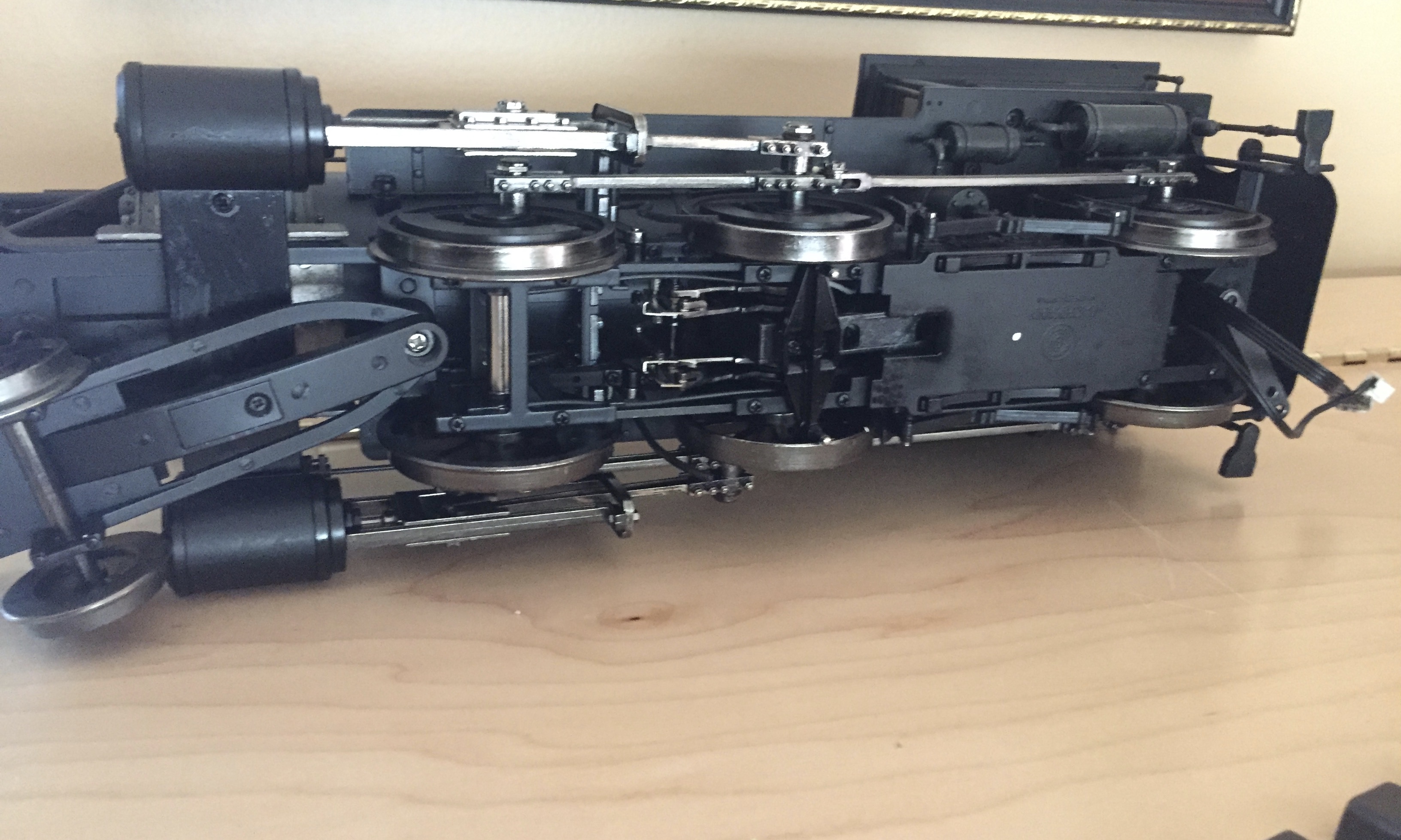
The solution is to remove those studs. Turn the locomotive upside-down, and observe the studs, near the centre drivers. Remove the screws holding them in place, BUT…DO NOT replace the two screws over the axle, as they will bind on the axle.

This should fix the problem.

There were never any reports of any problems, running without those studs…

I have checked with several people about the accuracy of my memory, and this information seems correct. I used to own one of these locomotives, and “Slightly” remember removing the studs. It was a very long time ago…

Fred Mills

Actually, you can see the studs in the picture provided…right on the inside of the centre, blind drivers, so there is visual proof of what I remember…

Fred Mills

Ahh, that does sound familiar…

Thanks Fred

Yes, I agree, before tinkering with spacing, get or make a gauge and check the wheel gauge and track gauge, so that you know you are actually fixing the problem and not creating one.

By removing those “Studs”, you will NOT be creating any problem. It has been many years since the “Stud Problem” was discovered, and it is in all likely hood the problem Mark is having.

It is always good to check wheel gauge on any new equipment (Back-to-back), but the description of Mark’s problem leads directly to the original “Stud Problem”. It was probably Dave Goodson who originally discovered the problem, and solution. (I did check with him)

Fred Mills

Posted by Peter Bunce, MLS moderator, 2009:

Hi,

IF you have the big Bachmann Spectrum Mogul, check underneath to see if the center flangless wheel still has a plate on the base between the wheels, it is basically a diamond shape with a couple of shiny steel pins that are close to the inner face of the wheels.

It stops the wheels sling - take it off, and keep it safe in case you want to put it back to sell it. Now the center wheels will slide sideways more - it does not affect the loco, but give more room for that sliding motion.

That should help - give it a try, and remember where you put in a ‘safe place’ the bit + the two screws for possible later use!

Greg

I think Fred has nailed this problem. I do remember those posts between the center drive wheels when I was repowering the locomotive with battery. I just had forgotten about those guide posts when I experienced this issue yesterday. These forums are great for helping one see a solution to a problem such as this one. Unfortunately I am not home today to try this fix, but I should be able to try Fred’s fix tomorrow afternoon. I’ll let you all know how it goes. Thanks to all for the responses. Best to all, Mark

Fred Mills. said:

Unfortunately you guys have missed the problem completely.

On that B’mann, Spectrim 2-6-0, they (Bachmann) were worried about the centre drivers (Blind as they are) falling off the rails on curves, and in this case, switches.

So, in their wisdom, mounted studs on each side to prevent that from happening.

The solution is to remove those studs. Turn the locomotive upside-down, and observe the studs, near the centre drivers. Remove the screws holding them in place, BUT…DO NOT replace the two screws over the axle, as they will bind on the axle.

This should fix the problem.

There were never any reports of any problems, running without those studs…

I have checked with several people about the accuracy of my memory, and this information seems correct. I used to own one of these locomotives, and “Slightly” remember removing the studs. It was a very long time ago…

Fred Mills

Way to go Fred! Your wisdom is appreciated.

Update: I removed the two pin assembly from between the center drive wheels and now the locomotive operates perfectly through all the switches in either direction! Problem solved! Thanks again everyone for your input and to Fred Mills for the solution! We are rolling now!

Mark