Large Scale Central

Ultima 10 amp power supply with melted diodes

Hi all. My railroad is shutdown until I find replacement diodes for my 1997 vintage Ultima 10 amp power supplies. I’ve emailed Scott Polk 3 times over the past 2 weeks and get no replies.

Does anyone have a part number or source to get replacements? There is no part number on the diodes in the Ultima. space is a bit tight in the case, so what has anyone else used for replacements? What diode values should I be using?

When money becomes available I am going to replace the Ultimas with Mean Well 24v dv 14.6amp units as many of you here use them with great success. Does anyone have a nice wiring flow chart to correctly wire the TE receivers to the mean Wells? which receiver wire goes to positive post on Mean well and which receiver wire goes to negative mean Well post and which wire and where should I put an inline fuse as an additional safety measure for the receivers and locos? Etc??

Especially need to get the diodes replaced in the Ultima so we can run the railroad empire again.
Thanks for any help.
Dick

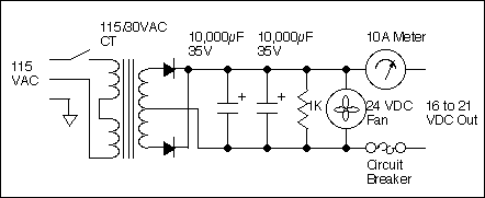
Dick - can you post a photo of the damaged area of the power supply? I found some information on that power supply here:

http://www.trainweb.org/girr/tips/tips4/art-5460_tips.html

It appears that there are only 2 diodes - If they are, indeed, the culprit you can find replacements on eBay - I found these 10 amp diodes

http://www.ebay.com/sch/i.html?_sacat=0&_from=R40&LH_BIN=1&_nkw=10+amp+diode&rt=nc&LH_PrefLoc=3

You could also use diodes with a higher rating just to be safe - the important thing is to put the new ones in with the same orientation (silver band at one end) as the ones you pull.

dave

You could call Navin:

201-565-6069

crest [email protected]

He was/is the electronics guru for the former Aristocraft.

Richard, Dave Bodner is correct.

But for Aristo/Crest electronic questions I would try contacting Navin at Crest. He should know.

Hi David and Lou. I am not having any luck posting pictures yet.
I’ve look at George Schreyer’s site, the schematic doesn’t show the 2 diodes.
I’ve earmarked all of those diodes on ebay as well.
I’ve emailed to the new site Scott has up and running now selling the Aristo Revolution, but am not getting replies. Is Navin working with Scott on this restart.

David would I look for 35v 10 to 15amp diodes perhaps?
On the Ultima the 2 diodes are encased in a long slender piece of plastic with a heavy duty male blade connector on both ends to hook the transformer wires to. The long slender plastic piece is riveted to the heat sink. There are absolutely no markings to show which end is which on the diodes unit. The yellow center wire from the transformer connects to a male blade that is riveted to the heat sink. The diode unit is mounted vertically on the heat sink so that one diode is on the bottom and the other on top. Because there are no markings at all, I don’t know which way to orient a new pair of diodes. The plastic unit that the 2 diodes are encased in also has an extra plastic pin that fits in a particular hole on the heat sink to orient the diodes correctly as long as one remembers to connect the correct yellow wires from the transformer to them.

The long slender plastic unit with male blade connectors lends itself nicely to fit in the narrow space in the ultima. I don’t think the post type diodes will fit in there.

If anyone has peeked inside an Ultima, he will see the plastic diodes unit I need.
I’m thinking Greg Elmassiun has probably looked inside one.

I’ll keep trying to post a picture. In the meantime, David would 35v/10 to 20amp diodes be okay then?

and again, does anyone have a wiring flow chart to correctly connect TE receivers to a Mean Well supply and also to show which wires and where to connect inline fuses?

And thank you all for your time and help.
Dick

**Richard Chapple Sr said:**I’m thinking Greg Elmassiun has probably looked inside one.

If you think he has your answer, contact him!

Richard, Navin is with Crest, I do not believe he is working with Scott on anything, at least not officially.

Dick — do the diodes look like this:

http://www.highpowersemiconductors.com/admin/uploads/semiconductors/thumb_1973.jpg

I should think that you would want a diode that could handle more than 10 amps - 35 volts should do it but I would be happier with something closer to 50 or 100 volts.

Give Navin a call - perhaps he has replacements in stock that would be an exact match.

If you live anywhere near Pittsburgh I would be happy to have a look!

dave

I agree, if you want to run 10 amps, you need a higher rated diode/rectifier.

It would be nice to know what the circuit breaker kicked out at.

Higher voltage too as Dave said.

Pretty easy to use almost any diode/rectifier with the right rating.

George’s old site (first link Dave had) shows the diodes, and George’s current site:

http://www.girr.org/girr/tips/tips4/art-5460_tips.html

Both show the diodes in the schematic, they are the things with the arrowheads and the line.

If nothing else email Dave or I the picture.

Regards, Greg

Hi Greg, thanks for helping out. I see the diodes in the schematic now. I see where it is prudent to go beefy for diodes.

I’ll email the pictures.
Thanks Lou for Navin’s number. I will call him Monday.
I will email pictures now.

Dick

I would use diodes with a rating of 100 volts and more than 10 amps as my unit with no load had 22 volts on the output and this gives around 45 volts for the PIV Peak Inverse Voltage), thus with a safety factor of double the PIV, I use 100 volts for diodes in large scale.

I did replace mine a long time ago when the diodes failed.

I got the pictures, there is a plastic bracket holding 2 diodes to a metal plate, the diodes are in cans, the top of the can is pressed against the plate, electrical and thermal conductivity, the other ends of the diodes have spade lugs on them.

Probably real hard to find the replacements, might use “post mount” type diodes like this, threaded into the metal plate:

Here’s George’s schematic from his site:

You can see that the common needs the polarity reversed from the picture above, i.e. the metal plate needs to be connected to the anodes…

I’ll look for the original type diodes…

Hi Dan. Did you replace diodes in an Ultima power supply? did you use post diodes such as what Dave B and Greg mentioned?

Thanks everyone for your input. It all has been helpful. I know once this power supply gets fixed, I am replacing them with some Mean Well units.
Dick

These should be the proper polarity to mount in the plate:

http://www.allelectronics.com/make-a-store/item/1n1190a/40-amp-600-volt-rectifier/1.html

Regards, Greg

Alright… thanks Greg. I may get 4 of them, just so if the other Ultima diodes blow I can fix it as well. The price is right too.

Please excuse my ignorance here, when I reconnect the two outside transformer leads to the diodes it should not matter which one goes to each diode should it? Of course the center wire will reconnect to the post directly to the heat shield.
Dick

Correct, this is a center tap transformer, and there is no polarity to the leads.

The center tap of the transformer should not be connected to the metal plate that has the diodes attached… it needs to “find” the negative side of the filter capacitors, and eventually the black wire or minus or negative terminal.

The spade lug on the metal plate should go to the red, plus, positive side of the capacitors.

Send more pictures of the larger assembly.

By the way, using a center tapped transformer means only 2 diodes are needed to convert to DC, whereas a standard transformer needs 4.

Regards, Greg

General info,
The original diodes were 50A buttons held against a steel plate by the plastic cap. 2 things cause your problem, a) the steel corrodes causing the contact resistance to rise, b) the plastic creeps with age and heat reducing contact pressure again more contact resistance. To fix it getting diodes is the easy part, getting new plastic and fastening at the correct pressure is the hard part.

Dick,
Go with new 50A stud diodes, use a nut and lock washer to mount them, the washer does 2 things, keep the nut tight, and keeps pressure as things heat and cool. Also the steel plate is marginal for getting the heat away. I strongly recommend using an aluminum plate. At least .060" thick, .090" or .100" is better.

When you get the diodes make sure they have cathode studs, the one in the picture has and anode stud. If you are using the 10 amps you will need 50A diodes because the peak currents are far above the average 10A.

Butch

When using Stud mount Diodes it is best to also use heat sink compound to get good heat transfer from the diode to the heat sink plate.

The link I provided has the proper polarity, and I already indicated as much.

These should be the proper polarity to mount in the plate:

http://www.allelectronics.com/make-a-store/item/1n1190a/40-amp-600-volt-rectifier/1.html

Good evening everyone. Greg, got the diodes ordered and on the way. I ordered 2 extra so if need be I can do my other Ultima as well.

Hey another Richard and Butch…great names…obviously I am a Richard and my nickname is Butch. Thanks for all the great info guys. Do you think Vaseline which is an excellent electrical conductor work okay?
Dick