For the piles I used 1/4 inch square lumber, for the bracing I used 1/4 by 1/8 and the sway braces (the Xes) I used 1/8 x 3/16th. I was going for a delicate looking, narrow gauge, shoestring look. For a mainline look, you may want to go larger, but not by too much.
GAP said:
Some more questions;
- For the bents what are the dimensions that folks used of each individual upright post.
I have 19mm (about 0.75") wide timber and was thinking of just ripping it to make 19mm square pieces, would they be too large?
What dimensions are the horizontal pieces across the top between the bents, looking at the pictures they appear to be the same as the posts that make up the bents, is that correct?
What dimensions were used for the bracing timbers, looking at the pictures they appear thinner than the other timbers, I’m thinking about 19mm x 9mm (0.35") does that sound OK?
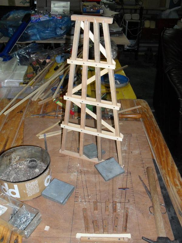
i used 10 by 10 mm (3/8 by 3/8") for the bents (vertical and horizontal)
the braces/boards are 11 by 2mm (13/32 by 1/16")
the running beams below the ties/sleepers are 10 by 16 mm (3/8 by 5/8")
the ties/sleepers are cut to the LGB dimensions.
but my trestle is just one and a half foot high at its highest point. for a much higher trestle that might look too spindly.
Is there any reason for leaving off the wooden guard rails at the ends of the tie’s, and the metal ones between the rails ?
I know, and accept that “Some” railways did not use the steel rail, guard rails, but most did include the wooden ones. The wooden ones are on the drawings, but the pictures posted of your models don’t show them.
I’m starting to build a new trestle to replace a thirty year old one. As the first one was built. I’m doing the same. We build the deck first, using two stringers (Sized to represent the four under each rail) and gluing/pin nailing the ties to the stringers. The deck will be mounted on an abutment at each end (It will actually be self supporting) then the bents will be trimmed to fit under the deck. looking as if they support the deck. (The stringers cannot be seen close enough to see that they are not individual timbers).
The rails, and both guard rails will be spiked to the deck before being mounted on the abutments. The running rails are code 332, and the guard rails are code 215.
We are using Titebond III waterproof wood glue, and pin nailed. The bents are being fabricated in a jig. They will be slightly over height to adjust for the varying space below the deck. All wood is Western red Cedar, which on the original, lasted 30 years.
As Bruce said; we are not trying to apply all the bracing, as it is too hard to keep leaves etc. from accumulating between the bents. Most people will fail to notice. They are more aware of lacking guard rails, it seems !!
Fred Mills
Fred Mills. said:
Is there any reason for leaving off the wooden guard rails at the ends of the tie’s, and the metal ones between the rails ?
I know, and accept that “Some” railways did not use the steel rail, guard rails, but most did include the wooden ones. The wooden ones are on the drawings, but the pictures posted of your models don’t show them.
I’m starting to build a new trestle to replace a thirty year old one. As the first one was built. I’m doing the same. We build the deck first, using two stringers (Sized to represent the four under each rail) and gluing/pin nailing the ties to the stringers. The deck will be mounted on an abutment at each end (It will actually be self supporting) then the bents will be trimmed to fit under the deck. looking as if they support the deck. (The stringers cannot be seen close enough to see that they are not individual timbers).
The rails, and both guard rails will be spiked to the deck before being mounted on the abutments. The running rails are code 332, and the guard rails are code 215.
We are using Titebond III waterproof wood glue, and pin nailed. The bents are being fabricated in a jig. They will be slightly over height to adjust for the varying space below the deck. All wood is Western red Cedar, which on the original, lasted 30 years.
As Bruce said; we are not trying to apply all the bracing, as it is too hard to keep leaves etc. from accumulating between the bents. Most people will fail to notice. They are more aware of lacking guard rails, it seems !!
Fred Mills
Perhaps GAP or Grame would like to run Amtrak someday Friar ,Padre,Father or whatever “nickname” you prefer as this was his original post/question that you didn’t really answer for him?
Fred, to be correct, I should have used longer ties, spaced closer together, with the added guard rails and beams you mentioned. But to hand-lay that much track, and then put it outside, with all the forces that are working to destroy what I put outside, didn’t seam like a good use of my limited time.
Fred Mills. said:
Is there any reason for leaving off the wooden guard rails at the ends of the tie’s, and the metal ones between the rails ?
in the case of my trestle there are fiftyeight point four reasons.
58.4 cm (23") being the avayable space for three paralel tracks of differing and opposing grades. (plus some landscapeing)
for using wooden guard rails the deck would have had to be about two inches wider. (not even to mention spaces for fire barrels)
a two inches wider footing of the bents was simply not possible.
metal guard rails of 332 LGB would have looked too massive for my taste. importing six meters of smaller rail from north america or europe wasn’t worth the trouble to me.
a desired sidekick was, that the slim construction results in an enhanced impression of length.
in hindsight, i could/should have made the spaces between the sleepers/ties smaller. (now the spaces equal the width of the sleepers)
OK after thinking about sizing based on the suggestions from David and Korm I redrew the trestle template.
I have decided on 12mm x 12mm (approx. 1/2") posts and 15mm (19/32") x 6mm (15/64") as the sills for the bents, cross pieces still be worked out.
I spent all this morning ripping 15mm x 6mm pieces of timber out of offcuts of merbau (a hardwood) decking board.
After doing all the cutting I was just dreading cutting all the timber for the posts (merbau is really hard and does not rip well) so I went to the local hardware warehouse and bought 30 12mmx12mm x 900mm (35.5") long hardwood garden stakes.
I made a trestle years ago out of the same stakes but they rotted off at ground level after about 7-8 years. As this trestle will be 1Metre above the ground that will not be a problem. The idea for using garden stakes came from a guy who owns the Sandstone & Termite railway in Sydney Aust.
Next up will to be make a jig to assemble the bents.
This trestle will be a curved one about 7Ft long on a 4% grade with the highest bent being about 380mm (15") high and the rest tapering down from there, similar to the one Korm has built.
Board to right of stakes is what I am ripping 140 mm x 19mm and hard (can’t be nailed with predrilling so I can forget about a pin nailer), but not as hard as what is being used for the road base support.
I am using an exterior water resistant glue similar to Titebond II.
Guard rails and water barrel shelves will be considered but as the RAGS construction company is doing the build they may not be included. (RAGS = Rough As Guts and old Aust description of any shonky/dodgy build)
To be “correct” the bent design is tilted a bit for a curved trestle. The outer piles have more lean to them then the inner piles. If you have ever seen a wooden roller-coaster, that effect is exaggerated to the maximum on the curves of a roller coaster. For a typical railroad trestle, that difference in pile angle between the inner and outer pile is only a few degrees, maybe 10 or 15 degrees.
OK some progress has been made, a jig has been built and work started on building the first bent.
Then it all came to a crashing halt when I tried to put the cap across the top of the bent posts.
The timber I planned on using is to thick for the nails I have so I have resorted to using the garden stakes timber.
How did folks nail / screw / attach the cap across the top of the posts?
Looking at Korm’s pictures it looks like some of staple was used is that correct?
aye. staples used are 8mm galvanized hardened steel.
used them fom both sides, for the caps and for the footers.
Korm Kormsen said:
aye. staples used are 8mm galvanized hardened steel.
used them for both sides, for the caps and for the footers.
In a gun or hand driven?
Well the first bent has been made so now its only 41 more (to make the 7’ length with spacing of 6") on a curve elevated 1Metre above the ground.
How hard can this be to build?
After a bit of mucking around I found a way to nail the cap across the posts, basically I drilled the cap and used a punch to drive the nails in the posts just had to be held firm by a piece of wood across where the mud sill would end up.
Pictures of the jig and the first bent attached. Apologies for the sideways orientation but I just cannot do pictures on this site well.
Great start … Make them all the same … when it’s time to adjust for height… I will cut the bent on my table saw by running the cap along the fence giving me my height … easier than trying to measure and cut each bent … You might need a piece of shim to get the bent level … (http://largescalecentral.com/externals/tinymce/plugins/emoticons/img/smiley-laughing.gif)
GAP said:
Well the first bent has been made so now its only 41 more (to make the 7’ length with spacing of 6") on a curve elevated 1Metre above the ground.
How hard can this be to build?
After a bit of mucking around I found a way to nail the cap across the posts, basically I drilled the cap and used a punch to drive the nails in the posts just had to be held firm by a piece of wood across where the mud sill would end up.
Pictures of the jig and the first bent attached. Apologies for the sideways orientation but I just cannot do pictures on this site well.
I’ll say. No picture in any orientation.
Photo inserting
- Start by uploading your photos to a server. You have storage space in the Freight Shed on this web site.
- After they are uploaded, click on the file you want to open.
- Once it is opened, RIGHT click on the picture and select copy image location. DO NOT use the url in the address bar of your browser.
- Next click on the insert photo button in your post and paste the image location in the source line.
- Look at the dimensions. You will see them if you click on the first box (height). Make it 800 then click on the second box and it will automatically be correctly scaled.
- Then hit OK and your photo will be in your post.
Sean McGillicuddy said:
Great start … Make them all the same … when it’s time to adjust for height… I will cut the bent on my table saw by running the cap along the fence giving me my height … easier than trying to measure and cut each bent … You might need a piece of shim to get the bent level … (http://largescalecentral.com/externals/tinymce/plugins/emoticons/img/smiley-laughing.gif)
Thanks for the tip Sean will give that a go, I was going to custom build each bent.
GAP said:
Korm Kormsen said:
aye. staples used are 8mm galvanized hardened steel.
used them for both sides, for the caps and for the footers.
In a gun or hand driven?
an oold “single action” gun from '68.
about the diagonal cuts:
i drew some horizontal marks on the jig. (in my case many, for the many different lengths of bents)
then i pushed the two outer beams against the upper stopper and sawed them off at the mark for the upper horizontal.
after putting the upper horizontal in its place, i pushed all four beams against it, stapled them to the horizontal.
at the desired length i sawed off the beams (all four at once) with an iron saw. (they are long enough to get all four with one cut)
after stapling the footer to the beams, i turnd the whole bent over in the jig (thus confirming it to be simmetrical) then stapled connections from the other side.
at last i nailed the horizontal and diagonal boards to the bent.
no glue involved.
the description took me longer, than making a bent.
ps:
for nails i used soft shoemaker nails. they don’t go in straight.thus giving some force against being drawn out.
Korm Kormsen said:
GAP said:
Korm Kormsen said:
aye. staples used are 8mm galvanized hardened steel.
used them for both sides, for the caps and for the footers.
In a gun or hand driven?
an oold “single action” gun from '68.
about the diagonal cuts:
i drew some horizontal marks on the jig. (in my case many, for the many different lengths of bents)
then i pushed the two outer beams against the upper stopper and sawed them off at the mark for the upper horizontal.
after putting the upper horizontal in its place, i pushed all four beams against it, stapled them to the horizontal.
at the desired length i sawed off the beams (all four at once) with an iron saw. (they are long enough to get all four with one cut)
after stapling the footer to the beams, i turnd the whole bent over in the jig (thus confirming it to be simmetrical) then stapled connections from the other side.
at last i nailed the horizontal and diagonal boards to the bent.
no glue involved.
the description took me longer, than making a bent.
Many Thanks Korm you have been a great help.
The first bent is installed now it is only a matter of doing the other 13 too cover the 14Ft gap.
looks good to me.
but don’t get hasty. good things need their time.