Very inspirational Gary. Enjoying this an being very much motivated. I’ve bee looking at discover live steam here and there and you’re right it’s not inexpensive. My plan is to order 200" of track in October. Keep the updates coming, I looking forward to the installation of the propulsion equipment.
Randy Lehrian Jr. said:
Very inspirational Gary. Enjoying this an being very much motivated. I’ve bee looking at discover live steam here and there and you’re right it’s not inexpensive. My plan is to order 200" of track in October. Keep the updates coming, I looking forward to the installation of the propulsion equipment.
Randy,
I had about 120-140 feet of West Coast rail (code 1000) (60-70 feet of track panels) that I bought from Chet Peterson when he owned Railroad Supply Corp. here in Burbank. That was in the very early 1980’s. I used wood ties then Didn’t last very long, probably 5 years and they were hand spiked! When I started our little short line last year, that’s when I contacted Dr. Bill Zingheim in Washington. He sold the EP plastic ties and West Coast rail. I purchased that stock from him in January of this year. Since then, I have found a vendor near Orlando, FL that makes turnout kits (any custom switch that you want) and also sells West Coast rail (aluminum) at a very good price I believe it’s under a “buck a foot” and 5000 SS tack screws for $350. Your best bet is to order the ties from Enterprise Plastics in Kent, OH (close to you). They also sell West Coast rail for $1.35/foot. in 10 foot lengths. But you might be close enough to them to pick up the ties and rail and save a ton of money on shipping by UPS (but the rail has to be cut down to 8 ft. lengths to do that) Or even higher shipping through aa freight carrier and pay additional pallet charges.
When I bought my rail and ties from Northwest Foundry and Rail Supply (Washington), the total for the ties, rail (240 feet) and freight charges was about $875. He bends the rail to your specific radius at no charge. But I did purchase a code 1000 rail bender from Rich Eaton (Eaton Custom Engineering in Castle Rock, WA). You can bend aluminum rail with this tool very easily and only $250 including shipping. This is the same guy helping me with the “build” of this little Super Huskie critter.
I hope this helps you in figuring the cost in laying 7.5 inch gauge track.
Thanks Gary. I’m absolutely going to use the EP rail system and the plastic ties. I already have a spread sheet that figures the cost for me based the number of feet I type in. I hadn’t thought about my proximity to Enterprise Plastics, but they are definitely close enough to make the drive and save on some shipping. Thinking I need to go visit Lakeshore Live Steamers in Ohio too. Getting real excited about it. Thanks again for all this great info.
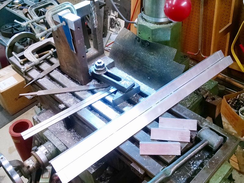
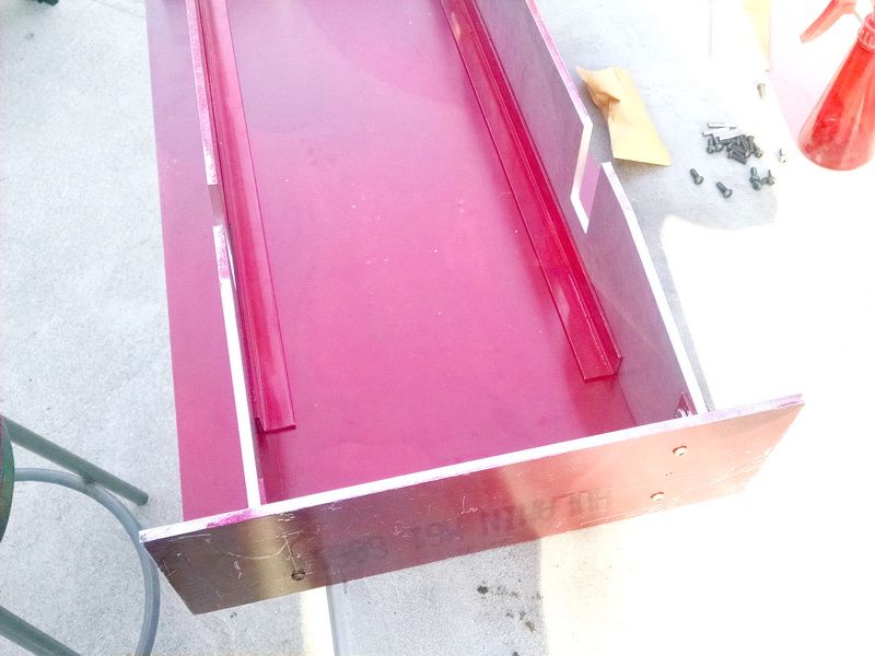
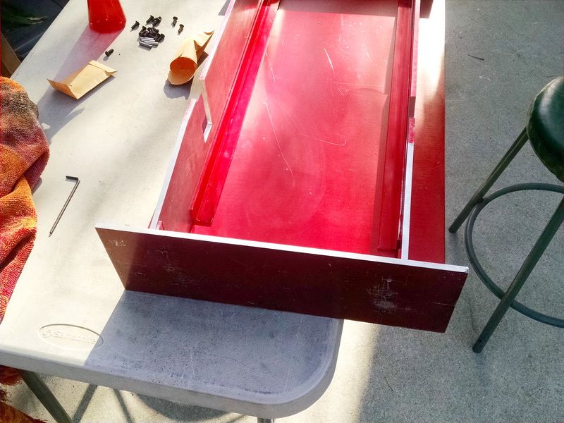
I have added a few more photos of the preparation and set up to center drill, drill and ream for the two 3/16 dia. dowel pins on the chassis side plates. Because I was a die sinker by trade for 42 years, I am a firm believer in pinning all my pieces together so that all pieces are located exactly left and right. Saves the problem of lining separate holes up for drill and exact match. Makes this engine strictly bolt-together. Everything is “dialed in” and no guess work. Takes a little longer at the start, but makes the rest of the milling and drilling very simple especially in relation to the right angle aluminum stock the fastens all the end plates and side plates together.
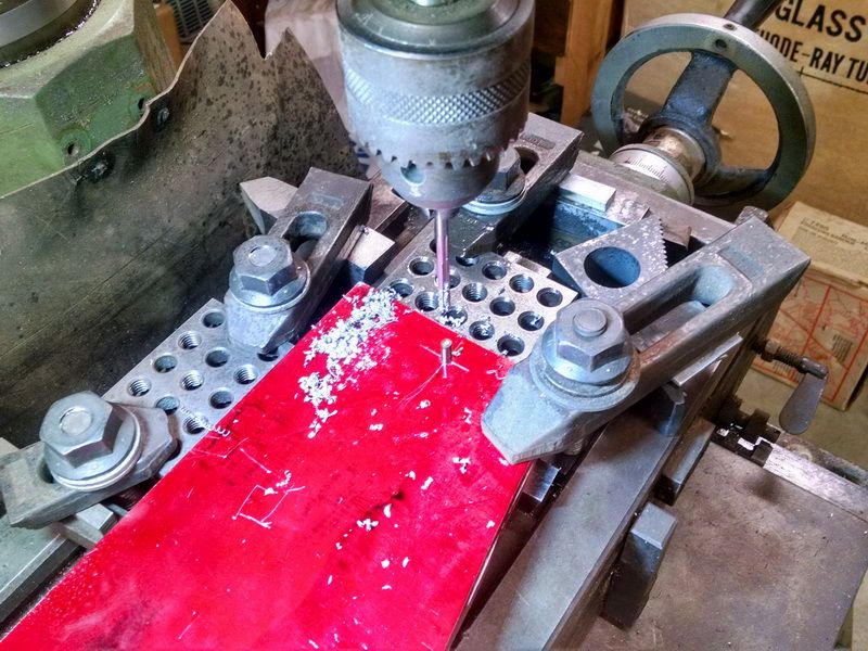
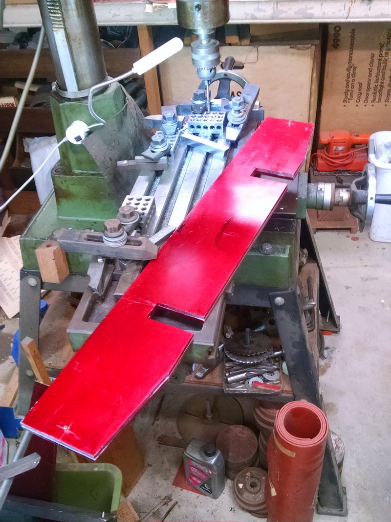
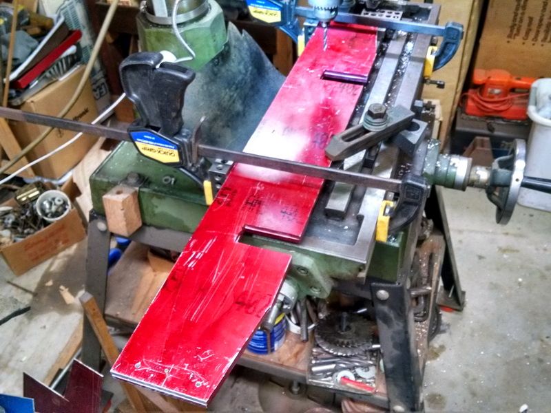
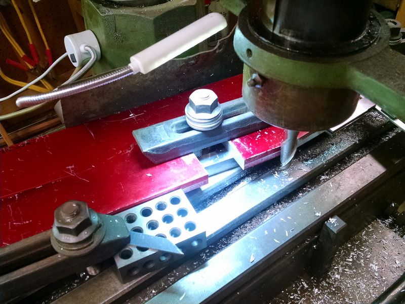
This first photo shows the general set up on my little mill for lining up the large aluminum chassis pieces. This aluminum is .250 thick, 32 inches long and 5 inches wide. Bigger than my mill table. So I set up precision 1-2-3 blocks as guides for the X and Y axis. Put .625 high speed toolbits as parallels to raise the stock above the table so that I could drill and ream all the way through BOTH pieces at the same time. Then I just turned over the two pieces and clamped them down on the mill table and against the X and Y 1-2-3 blocks and drilled the second set of pin holes.
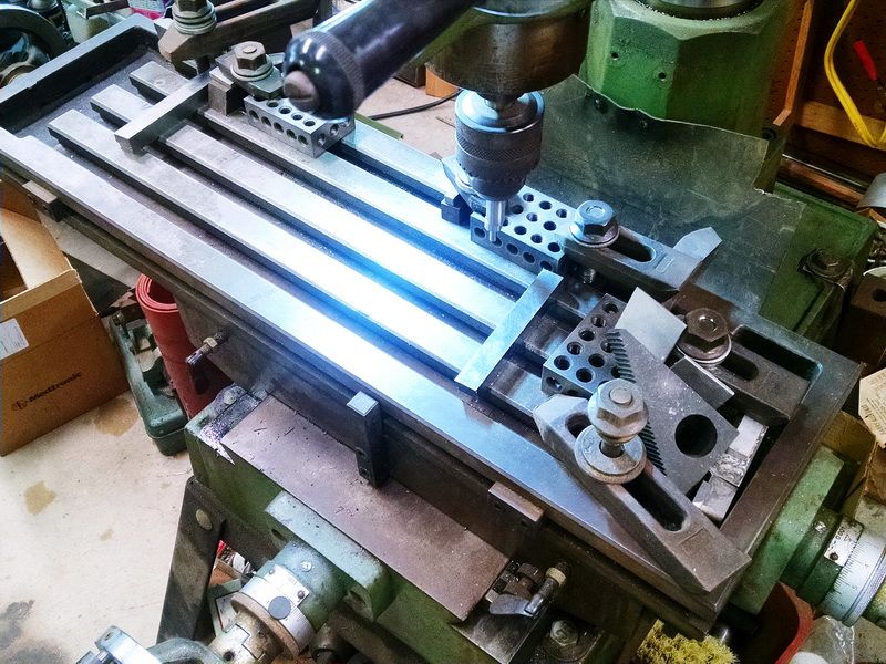
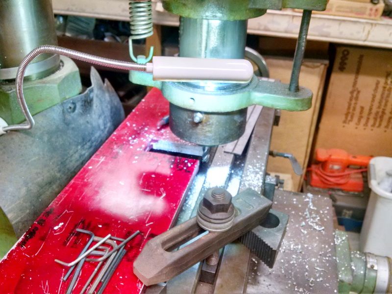
You can see the .200 diameter edge finder in the chuck. Once the stock was in place, I just set the edge finder (as it’s rotating at 600 rpm) against one edge of the stock. As you go a little bit more, the edge finder will move off center. That puts the center of the spindle half of .200 or .100 away from the edge. Set the dial on the mill and move it exactly .100 and that is the EXACT edge of the work piece. Easy from there to dial every location in using the dials on the mill. EXACT centers for all dimensions.
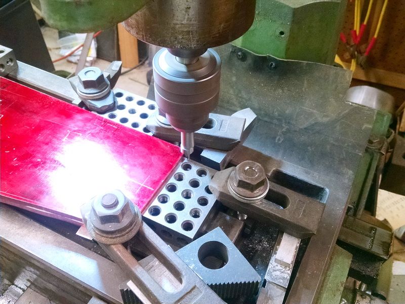
This is the set up for getting the X axis dimensions. Notice the spindle is on and the edge finder is off center. The spindle is .100 from the edge of the work at this point.
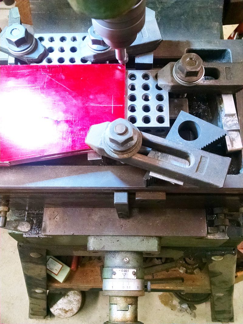
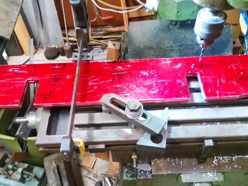
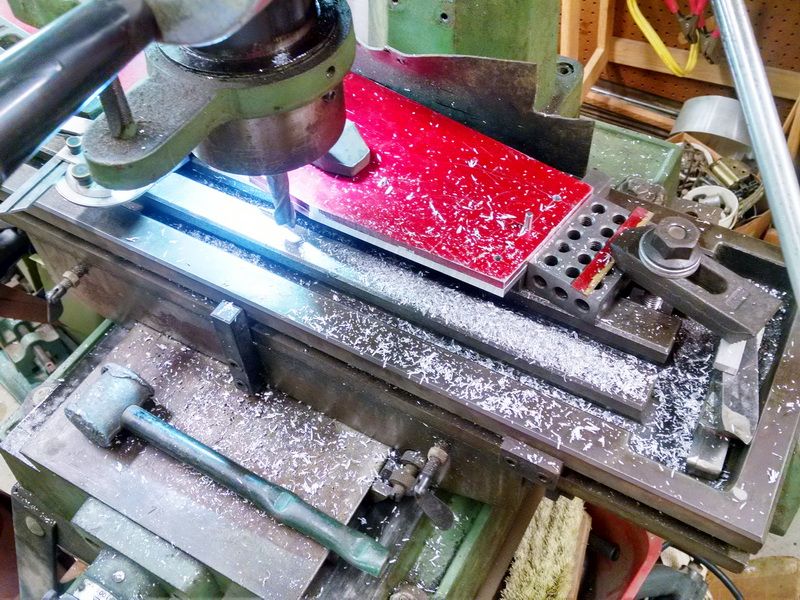
This is the set up for the Y axis.
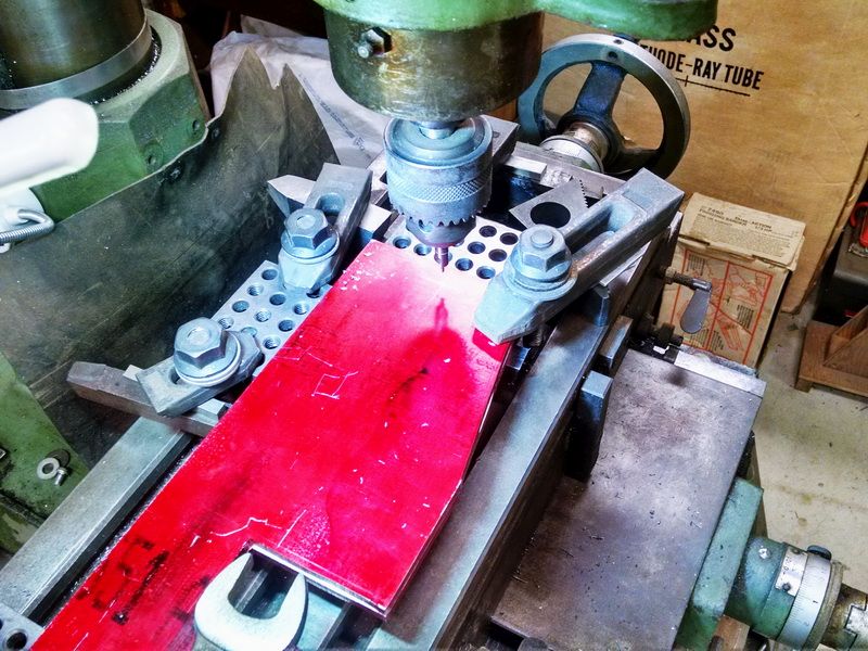
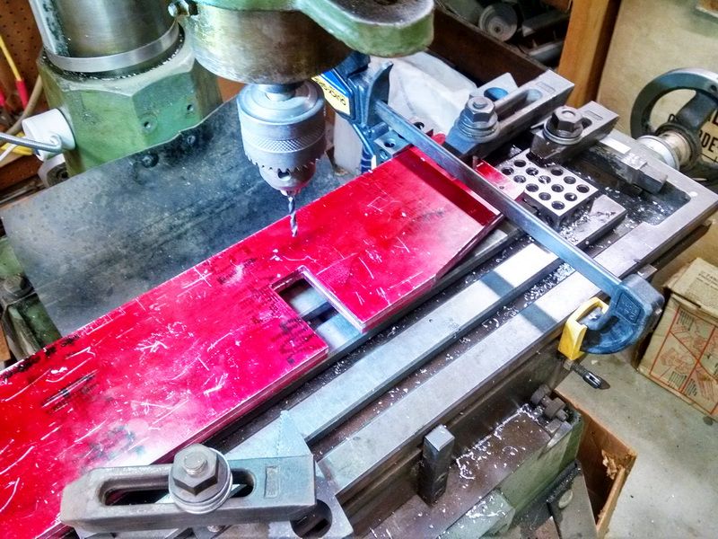
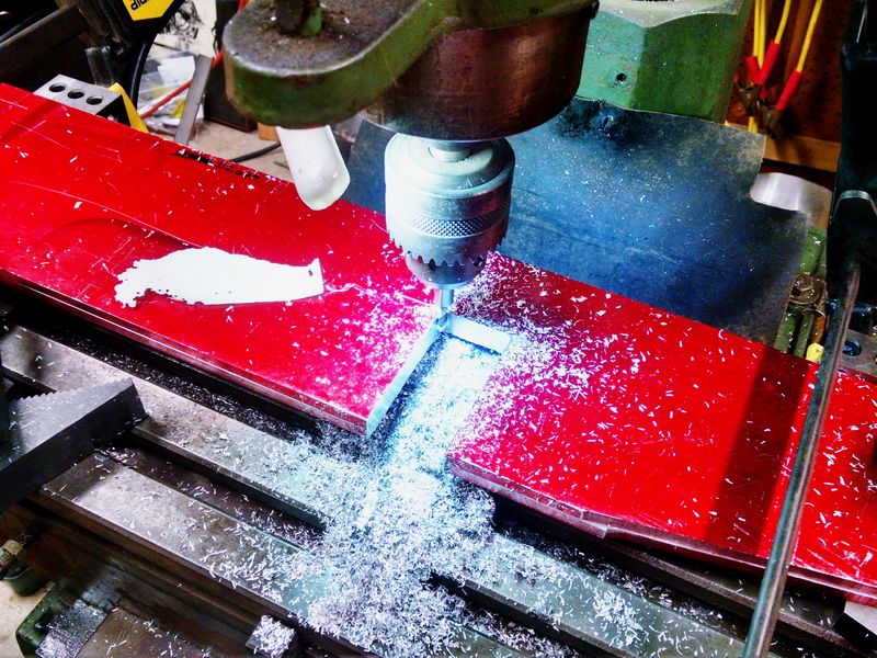
Center drill set up.
Reamer and 3/16 dowel pin.
Th two chassis sides pinned together ready to mill and drill as a matched set. The 3/16 dowel pin holes will eventually become bolts holes to fasten the end plates and side plates together. The hole with the pin will be enlarged when the parts are completed. Open the holes to .194 diameter for 10-24 button head bolts and nuts. This whole process is how you machine large parts to exact dimensions when you have a small mill.
Finished all the bolt holes for the end plate and side plates to get ready to bolt together the basic chassis. I still have the dowel pins installed on these plates so nothing can move. Made the set-up to mill the journal box pockets. I just continue to dial everything in and both pieces will be exact. In fact they can be interchangeable. Once these are finished milled, I will turn to my lathe and make the journal boxes. The slots in the journals will slide up and down in these pockets and the wheelbase will still be rigid.
The 1-2-3 blocks are clamped to the rear of the mill table. That area is finished ground and is absolutely parallel to the X axis. Once I clamped the two chassis side plates to the mill, I removed the 1-2-3 blocks and the clamps. Not needed anymore.
This shows the other 1-2-3 blocks on the match end and I never removed the stop block after the drilling operation. This way the locations I used for drilling are still in place for the milling.
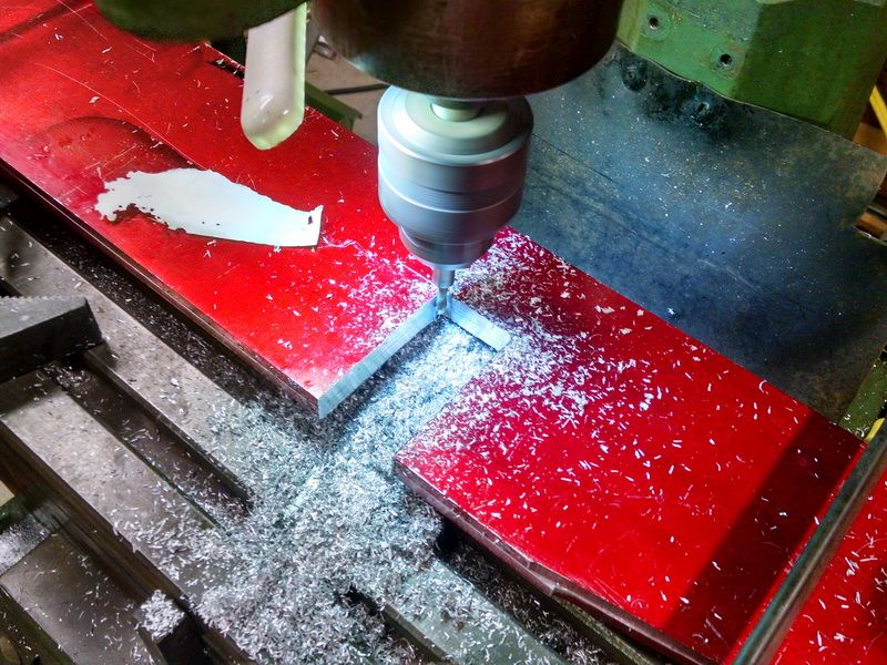
Starting to mill the pocket. When this pocket is finished, all I have to do is turn the plates over and mill the other pocket/pockets. The position will still be the same, so I just use the same dial readings on the mill table.
Continuing with more photos of the Super Huskie “build”…
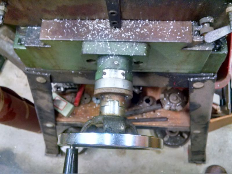
Finished the journal box pockets last night. Tonight I had a little time to “pick-out” the small corners at the top of the pockets. This is the area where the small aluminum block slides into the pocket and is the stop for the single coil spring. Theoretically this could be a sharp corner, but the aluminum block can be relieved to slide all the way to the top of the pockets. But this is still a small cutter 3/16 diameter and cutting 1/2 deep. Best way to do this is to use the cutter as a “broaching” tool and just raise and lower the quill. No spring that way and absolutely vertical the full 1/2 inch depth.
BTW, a side note here…the scrap piece of paper is actually a “tool”. After you finish milling a nice wall (such as these on the journal pockets, you sure don’t want to “mark” the wall with the smaller cutter as you set that cutter’s dial setting. To keep from doing that, you get a scrap of paper, measure the thickness of the paper (in this case it is .003. You dial the smaller cutter up close to the wall as you put the paper between the rotating cutter flutes and the finish wall. Slowly and carefully dial the cutter into the work piece until the flutes "just start to grab “grab” the paper. The cutter will actually pull the paper scrap out of your fingers when you are .003 away from the wall and the wall will NOT be marked. Depending on how “tight” your machine is, you dial another .002 farther in and you will be away from the work by .001. Close enough and the work is still pristine. You can also do this on a lathe.
The spindle is not running in this photo so you can see the cutter (0.1875 dia. and 1/2 inch flute, spiral HS). Notice I used a heavy duty Jacobs chuck for this. Not good machining protocol, but I needed to see the cutter. I could have used my 3/8 R8 collet, but then I really couldn’t see the cutter. A machinist “work-around”.
With the spindle running at 1000 rpm.
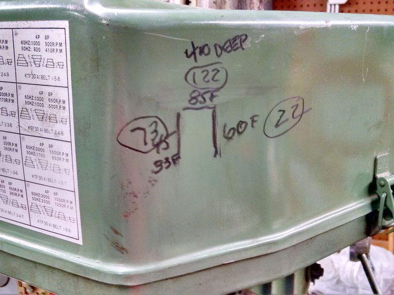
A little nachine shop “graffiti”. Grease pencil marks noting the table dial position for the pockets. The numbers marked with an “F” is the finish wall cuts for the large end mill and the “circled” numbers are for the 3/16 end mill for the corners only. When I turn these pieces over, I can then finish the small corners in the other pockets and still use these same dial settings.
Tomorrow I machine the angles on the side plates and then assemble the chassis for the first time including the bedplate for the cab and hood parts.
Keep em coming Gary. I’m really enjoying this. Looking forward to seeing the assembly in your next installment. It’s almost painful to watch, because I want to start making chips too but I’m months away from that at this point. I just got my machines moved up to our new place, and this coming weekend I go back for the rest of the shop equipment.Unfortunate ly I’m just cramming it all in the garage for now until I build the shop addition off the garage. I should break ground on that in about 3 more weeks. Thanks for keeping me motivated!

quite a project. . .
Gary,
What would you recommend for an edge finder? I’ve got a x/y table setup on my mini drill press and would like to start using it more. Seeing how you used the edge finder now makes a lot more sense in locating parts. Yes, its not a mill, and I don’t plan on using it to mill, but I would like to start learning the basics in case someday I can acquire a mill.
Thanks for the comments folks.
Randy:
I know how you feel about starting to make chips. I just sold my 90% completed 1-1/2 inch scale Gene Allen ten wheeler steam engine. I have been building it since 1981 as a kit. Between kids and family and eventually health issues, it just seemed like it was going to take more time to finally finish it. A young man at Los Angeles Live Steamers kept asking me if I wanted to sell and I kept putting him off. I finally decided it was time to sell it (I’m 73 and way too many projects going). The buyer is 28, a corporate jet pilot and has the funds and resources to finish it. He is now the new “caretaker” and has the engine running on air. And I have “other” locomotives to finish (seven (yes 7) 1/8th scale Baldwin P.E. electrics), a couple of pieces of 1/8th scale rolling stock. Also have a 7-1/2 inch gauge short line railroad to complete around the house!! Posting photos and dialog on LSC keeps ME motivated. When you get your rail and ties from Enterprise Plastics, you WILL be motivated!
Narrow Gauge Lover:
This Super Huskie critter is a nice project and so easy to build (with the proper tools, not for everyone though). Aluminum is so much easier to work with than steel. Easy on cutters and easy on machinery.
Craig:
Buy a Starrett model #827A or a #827B (double-ended). Mitutoyo also makes edge finders. I just prefer Starrett. Of course mine are over 35 years old.
https://www.amazon.com/Starrett-Edge-Finders-Single-End/dp/B007K35KAUI
This one would probably be your best choice for what you are using it for. have a couple of these and a double-end one (has a pointed end for locating EXISTING holes in your work piece).
Link to a double-ended edge finder:
Monday night update on my Super Husky build…
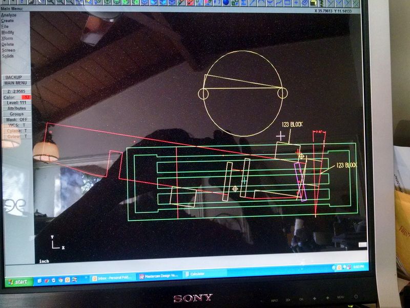
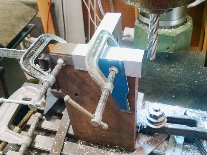
Cut the tapered ends to the side plates on Saturday. Did all the set-up calculations and trig on my computer using MasterCam. This computer program was also used to make our seven Baldwin P.E. box cab locomotives. All parts were drawn on the computer and the tool paths were programmed. Verified the cutter moves using the Verification module in the program. Then we set the parts up on a Haas horizontal CNC mill and also used an old Bridgeport Bandit mill. This system almost makes it too easy to build these 1/8th scale model locomotives :).
Using a 2-flute 3/4 inch diameter spiral end mill at 600 rpm and WD-40 as a lubricant/coolant.
You can see the Mitutoyo bevel vernier protractor in the background. Once I checked the angle on this first cut, I didn’t have to check the other three tapers. The 1-2-3 blocks were in place along with the stop block. Because the sides were still pinned in place, it was just a matter of flipping the pieces over and putting up against the fixture blocks. No checking, just use the dials again for the final cuts. Fixture set-ups can be a great time saver when doing similar multiple cuts over and over.
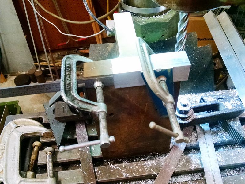
I milled the finish lengths to the 1 inch X 1 inch aluminum angle today for the four corner supports to assemble the side plates and the end plates of the chassis each 3-1/2 inches long and the two 1 inch X 1 inch X 24 inch long aluminum angle to attach the engine bed plate to the sides and ends. Using a 4-flute 3/4 inch diameter spiral end mill at 600 rpm and WD-40 as a lubricant/coolant.
That’s all for tonight. Tomorrow, I’ll layout the holes in the corner support and the bed plate support and hopefully have it assembled tomorrow.
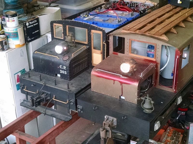
My two P.E. Baldwin electrics. Baldwin-Westinghouse 1600 series. The black engine #203 was built over 35 years ago as a Los Angeles Live Steamers 28 engine project. The unpainted sister engine was built entirely by computer including drawing and machining all parts. The old engine has Mercer Locomotive Sunbeam headlamps with an LED bulb. The new engine has Sunbeam Golden Glow headlamps custom made by Master Model Maker Jack Bodenmann. It uses Krypton gas bulbs. More realistic lighting and closer to what the Golden Glow prototype. Since this photo was taken last year, the old headlamps were completely remade by Jack and a new reflector and bulb and photo-etched glass number boards installed. I get delivery of these headlights at the LALS Spring Meet in a couple of weeks.
EDIT and update on the above mentioned Baldwin electrics:
As I mentioned before, the Baldwin P.E. box cab on your LEFT is about 35 years old and the Mercer Locomotive headlights are original to that engine. The electric on your RIGHT is a new engine and the headlights were made by a Master Model Maker named Jack Bodenmann.
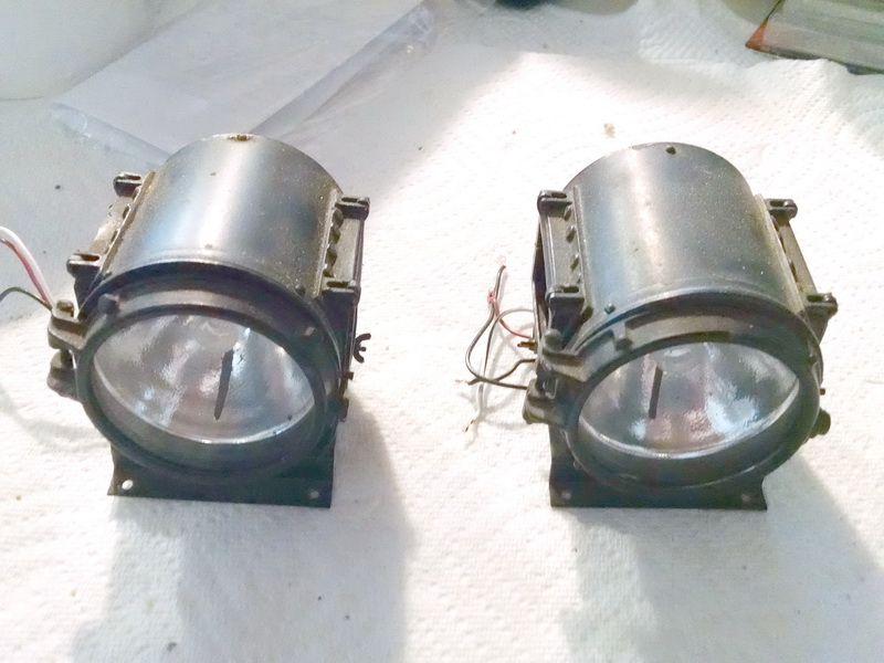
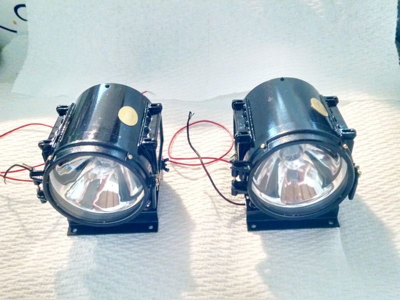
Today I picked up my old Mercer headlights after Jack rebuilt them. The following photos are the BEFORE and AFTER shots.
The BEFORE photos:
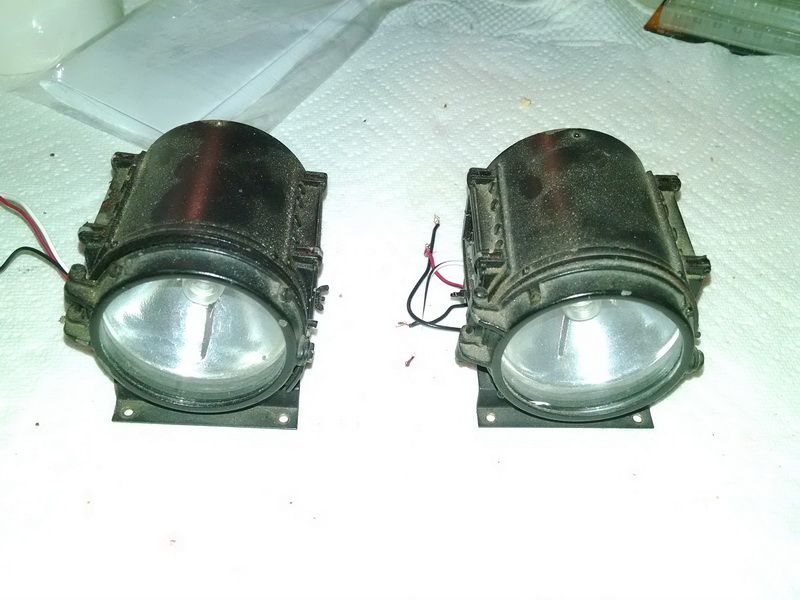
The AFTER photos taken this afternoon:
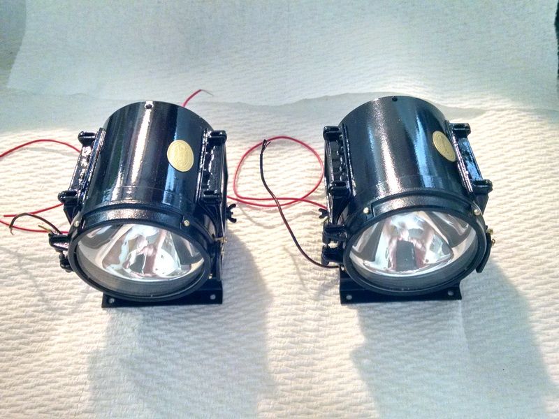
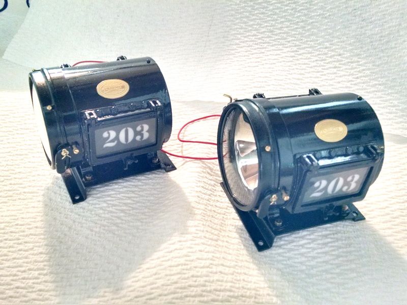
Brand new 3-layered glass photo-etched number boards, spin casting chrome plate reflector and illiminated by Krypton gas bulbs. He even repainted and added the micro-etched brass builder’s plate! Also note the curved glass bezel on the headlight face.
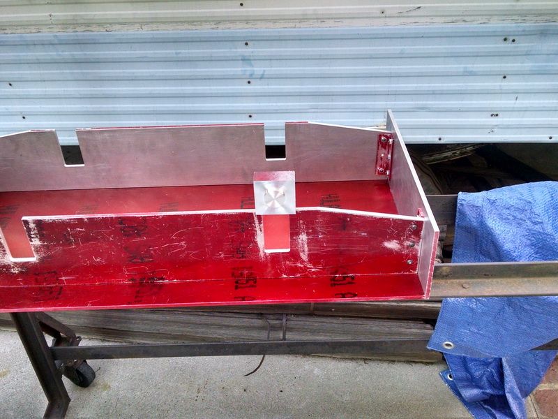
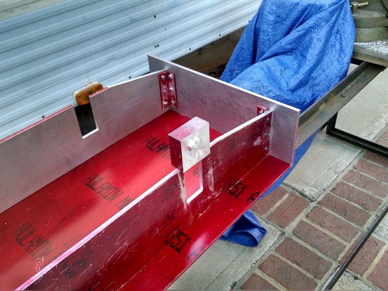
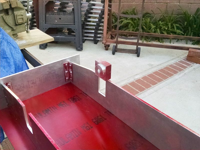
Today I was finally able to try all the parts together for a fit. Had to make sure all the drilled and reamed holes “lined up” and everything fastened together correctly. I ran out of fasteners before a complete assembly could be finished. I will get more tomorrow. But everything went together snug and tight. The frame came out absolutely “square” and “straight”.
Put the hood shell on for location.
Bottom side of the engine looking at the bed plate. I will leave the .1885 reamed holes in place before opening up these holes for the 10-24 button head screws. The reason for not enlarging the holes now is the I still need to mill out the coupler pocket rectangle in the front and rear end plates and provide the space for the coupler tang (which is roughly 7/8 inches square).
This photo shows the two 1 X 1 X 24 long angle aluminum that supports the sides and bed plate together.
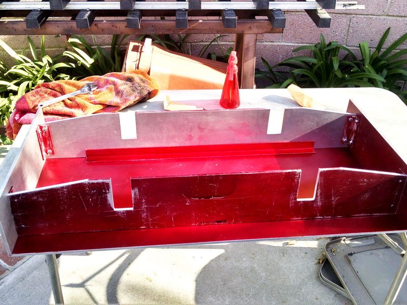
Here you can see the four journal box pockets in the side frames. Again, I machined these pockets with the two sides dowel pinned together so that the pockets are exactly opposite and 90 degrees to each other. No axle or bearing misalignment this way.
I have been preparing my older Baldwin electric for its “reworked” Sunbeam Golden Glow headlights. I will be picking up both headlights from the Master Model Maker who is doing his “magic” to these old Mercer Locomotive Company products (located in New Jersey). He added chromed copper “spin casting” reflectors, photo-etched glass number boards (3 layers of glass just like the prototype) and Krypton gas light bulbs. Our Spring Meet at Los Angeles Live Steamers is this coming weekend and the model maker will deliver them at that time.
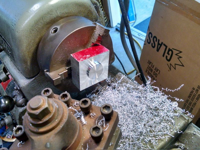
So I was finally able to get back to working on my Eaton Super Husky today. First step is to prep each block for milling and boring for the ball bearings for the axles. The bearings are sealed, 1.125 outside diameter and .500 inside diameter for the tip of the axles. The axle stock is CRS and 3/4 inch in diameter.
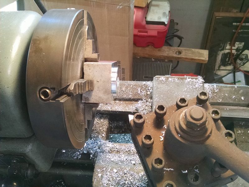
There are four journal boxes roughly 2 inches square. This first operation is to establish a 1.750 diameter round “match edge”. This enables me to turn the block around and “turn” detail on the front of the journal and keep the front detail concentric to the rear detail which is the bored hole that holds the ball bearing. In that operation, I will use my 3-jaw chuck which automatically centers the work. In this photo you can see the back face of the journal box. When I do the milling operation, this “match edge” will be used to CENTER the slots in the journal that slides in the milled pockets on the chassis frame.
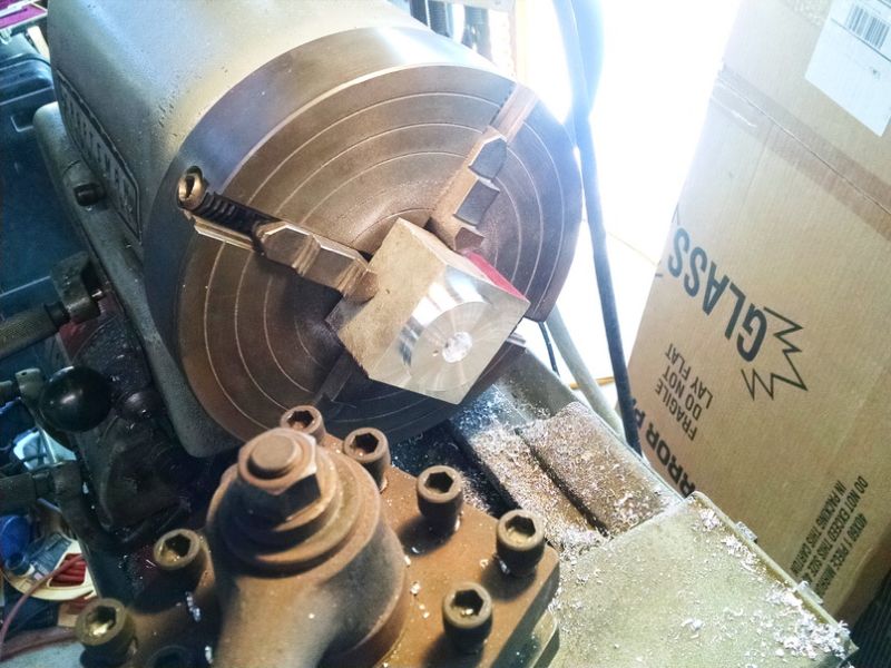
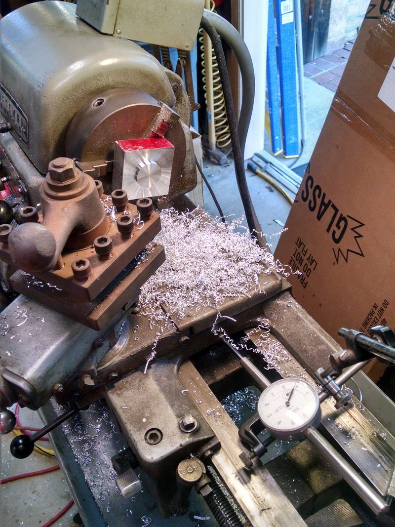
The drilled hole will help to start the boring job for the ball bearings. When the journals are completely machined and finished, this match edge will be machined away. Chuck it up in the four-jaw chuck and in a few minutes, it’s gone.

You can see the rough aluminum stock that I start with sitting on the lathe compound.
More lathe work tomorrow. And then onto the milling machine to do the slots.
I’m really enjoying this thread Gary… (http://largescalecentral.com/externals/tinymce/plugins/emoticons/img/smiley-tongue-out.gif)
Sean McGillicuddy said:
I’m really enjoying this thread Gary… (http://largescalecentral.com/externals/tinymce/plugins/emoticons/img/smiley-tongue-out.gif)
Thank you Sean :).
Started the lathe work on the front faces of the journal boxes today. Changed to my 3-jaw chuck and used the jaws that are used for INSIDE holding situations. Note that each jaw is numbered 1, 2 and 3. There is also a corresponding number on the face of the chuck plate. You turn the scroll on the chuck with the chuck key until the scroll comes to the #1 jaw position. Place the jaw in the chuck and engage the scroll to grab the jaw. continue turning the chuck key until the beginning of the scroll reaches the #2 jaw position, then insert the proper jaw. Continue with the #3 jaw until it engages the scroll. Now all 3 haws are moving in towards the center of the chuck and are lined up to be concentric to the center of the lathe spindle. I know this chuck is accurate to within a couple of thousandths, which is close enough for what I’m doing. If I wanted to be more accurate, I would use the 4-jaw chuck.
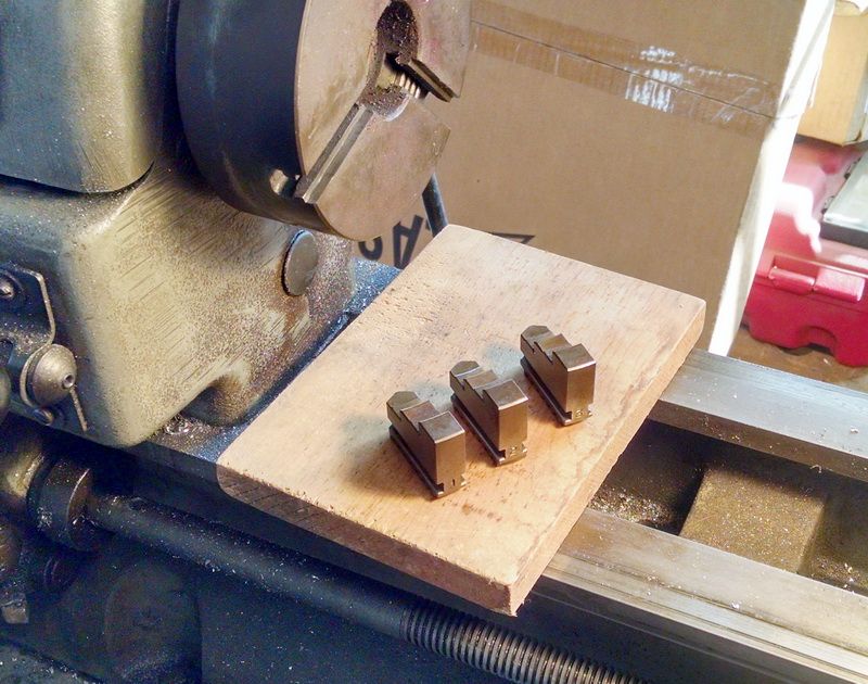
In this photo you can see that each jaw is numbered 1, 2 and 3.
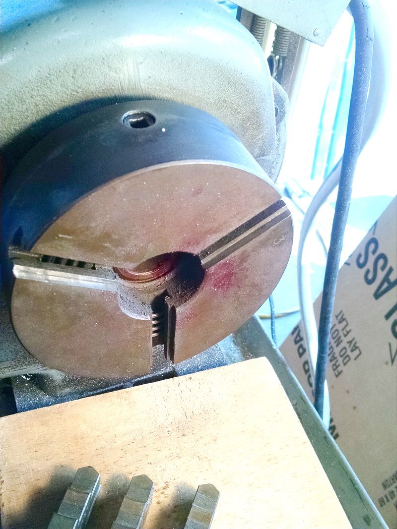
The corresponding numbers are shown on the face of the chuck. You can also see the scroll thread on the inside of the chuck and this is what engages the jaws as they move in and out. All three jaws move simultaneously and accurately to the center of the lathe spindle. This chuck is 6 inches in diameter and weighs about 20 pounds.
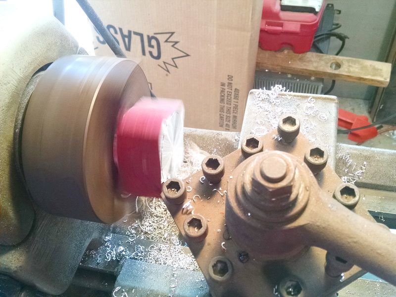
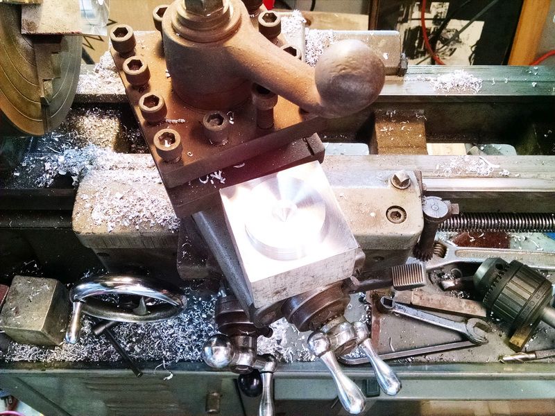
Turning the front face of the journal box.
1.125 hub face completed.
This is how I use an indicator to dial in accurate steps when turning on a lathe. The hub face is .125 above the face of the rest of the journal box.
First journal placed roughly over it’s new pocket. When I start the milling work, I will mill slots in the sides of the journal that will allow the journal to slide up and down with a single coil spring as suspension.
The backside of the journal box with the “round match edge” boss used to center the front face hub to the center of the bearing bored hole.
Sean McGillicuddy said:
I’m really enjoying this thread Gary… (http://largescalecentral.com/externals/tinymce/plugins/emoticons/img/smiley-tongue-out.gif)
Yea, ditto…(http://www.largescalecentral.com/externals/tinymce/plugins/emoticons/img/smiley-wink.gif)
Last time I did any machine shop work was in high school.
Ken Brunt said:
Sean McGillicuddy said:
I’m really enjoying this thread Gary… (http://largescalecentral.com/externals/tinymce/plugins/emoticons/img/smiley-tongue-out.gif)
Yea, ditto…(http://www.largescalecentral.com/externals/tinymce/plugins/emoticons/img/smiley-wink.gif)
Last time I did any machine shop work was in high school.
Tritto. (http://www.largescalecentral.com/externals/tinymce/plugins/emoticons/img/smiley-laughing.gif)
I worked for a summer in a machine shop owned by a friend of my father’s during one summer. That was back before all the ridiculous child labor laws came about, where kids couldn’t get that kind of experience. I remember doing a lot of sweeping. (http://www.largescalecentral.com/externals/tinymce/plugins/emoticons/img/smiley-tongue-out.gif)
I learned a lot, forgot most of it.
Thanks folks for the comments. One of the reasons I started this thread was to give those people who have never done any machining on a lathe or mill and to actually build something tangible from scratch, that there is nothing “mysterious” to this. You break a model down to it’s basic parts and start making them. Not only can it be done with a large ride-on model like this “critter”, but also models in the smaller scales like our garden variety trains.
Many years ago, I found a copy of Railroad Model Craftsman from before WWII. It described building a locomotive (probably 0 Scale) from scratch. The article opened with the phrase, “First, mill your driving wheels on your lathe.” That’s it. Nothing else on milling the wheels.
So much assumed knowledge, back then. So much lost.