Large Scale Central

Snow Dozer Build

John,

Thanks for the idea. I don’t have any accelerator on hand, but that is a good tip to remember.

Modeling has been put on hold temporary as I watch millionaires hit and catch a leather covered rubber ball.

I use a flame to clean out my needle applicator with MEK after styrene fills the end. Makes a nice flame thrower…

I also asked my dentist for old tools as well. I actually need to ask again as a few of them have broke. I sharpened on to make a tiny center punch/scribe.

The adventure down the rabbit hole has begun again. I thought I was done with the details on the drag wings, but when I studied the pictures again, I noticed that the drag wings in the later years had a metal safety tread on the top of the wings. This allows the MOW crews a safe walking place to chain down the drag wing at the end of the day.
So, I decided that I had to model this feature, and thus down the rabbit hole I went. The FRA regulates every part of railroad equipment standards, and the AAR publishes information that allows manufactures to build parts that comply with each and every regulation. AAR Standard 226 details running boards, ladders, and other safety appliances. I thought that I would be able to find the AAR standard 226 drawings and go from there. Well I don’t have $200-300 to spend on a 500 page instruction book for just one standard. So, using the power of the internet I found a technical drawing of a similar running board.

I fired up Sketchup and started drawing a sample piece.

Once I finish the drawing, I’m debating if I should have the part 3D printed or try my hand at photo etching either through a commercial service or homemade. These little rabbit holes are fun to dive into but can lead to some interesting results.

Craig

Shane would fabricate … nudge nudge … a thin top plate glued to two L angles. A paper punch pops out your large holes, slices of heat shrink tubing are the glued on rings(https://www.largescalecentral.com/externals/tinymce/plugins/emoticons/img/smiley-yell.gif), but please carry on … I kid(https://www.largescalecentral.com/externals/tinymce/plugins/emoticons/img/smiley-smile.gif)

So John, I posted this same question in another forum and found out that a company overseas makes photo etch steps, just like I’m looking for in 1/24th scale.

Your right, I probably could fabricate something myself as well. I have a nice xy table setup on my mini drill press, so once I have the spacing and hole pattern worked out, I could just drill them out.

Or this could be an excuse to learn a new modeling technique with photo etching. Looking at the program I would have to draw the parts in it looks like a steep learning curve!

Oh, I thought you were scratch building …never mind.(https://www.largescalecentral.com/externals/tinymce/plugins/emoticons/img/smiley-wink.gif)

John Caughey said:

Oh, I thought you were scratch building …never mind.(https://www.largescalecentral.com/externals/tinymce/plugins/emoticons/img/smiley-wink.gif)

Is not drawing the CAD design a function of scratch building? I fail to see or understand you comment. Regardless of where I get the parts, I have to assemble them, so isn’t that scratch building? Clearly I’m making a model that doesn’t exist in model form, so I would consider that a scratch build.

I was reacting to the idea you would buy them per the pic … sorry.

John Caughey said:

I was reacting to the idea you would buy them per the pic … sorry.

So buying a premade part that’s use is something completely different, is still not considered scratch built? I didn’t know we were using the NMRA definition of scratch built. In that case, I guess I shouldn’t have used the USAT running boards to build the end platform.

I’m not trying to get into to an argument, but I’m trying to understand your definition of a scratch build? An I taking the same approach as Shane? No, but we are both building one of a kind models.

John Caughey said:

Oh, I thought you were scratch building …never mind.(https://www.largescalecentral.com/externals/tinymce/plugins/emoticons/img/smiley-wink.gif)

Yunz see the wink? I believe he was kidding with you.

Up until now, most everything on this incredible build has been wrought with your own hands. To deviate from that trend elicited a comment in jest. Of course its scratch-built, even if some commercial detail parts are used.

Personally I like the FAA definition of home build for scratch-building. 51% of the build has to be done by the home builder to consider it home built. That means 49% of the thing can be shake the box detail parts, repurposed parts, commercial parts or what have you.

Craig Townsend said:

John Caughey said:

I was reacting to the idea you would buy them per the pic … sorry.

So buying a premade part that’s use is something completely different, is still not considered scratch built? I didn’t know we were using the NMRA definition of scratch built. In that case, I guess I shouldn’t have used the USAT running boards to build the end platform.

I’m not trying to get into to an argument, but I’m trying to understand your definition of a scratch build? An I taking the same approach as Shane? No, but we are both building one of a kind models.

I didn’t write the definition.

Maybe we should use one dictionary. My definition was pre enemaray. What’s wrong with 95% scratch and 5% parts built? Some Craftsman kits were better than ‘scratch’, it depends on the builder.

Please understand that in no way do I wish to demean your fine model, I wish you all the success possible.

I confess I didn’t read the whole post carefully and posted that semi-joking comment in response to the ‘other’ group’s; here is what we use.

Of course buying tread to use as tread is … sorry my new dictionary tells me to not go there.

Craig,

The custom laser cutter (Pololu) has some .024 and .03 Stainless you could laser your part as flat, and then bend it up like you would photo etch. If you want a 3D effect to the holes you could use a round object and punch it from the backside. I’m sure the real stuff is aluminum, so the stainless would give you close to the same look. Just an idea.

Chris

I’ve been plugging away adding details to the front cage assembly (this raises and lowers the front wings). Some of the details I have drawings for, and some of it is just plain old guess work. It’s actually been really fun to build with detailed drawings, and now I’m so invested into using them I want to find more. Anyone live in the St. Paul/Minneapolis area?

A few details have to wait until this sub assembly is on the model. One of those being a cover that covers the cable and pulleys from snow.

Some of the details include;
Lube/access plates for the truck wheel bearings, rear step with support bracket, and end safety chain.
(https://farm5.staticflickr.com/4555/25091766278_437d157b85.jpg)
On the front end;
More lube/access plates, front safety chain bracket, patch/weld replacement (including sloppy welding), and extended front plow. The pulleys also got the mounting brackets added.
(https://farm5.staticflickr.com/4540/27185896429_29c1a5b9d0.jpg)

Next is designing and building the moveable wings. The brass piece comes from my original snow plow model, and the aluminum one is from a pop can. This is where the guessing comes in place. I have no information on how big these wings are, or what shape they are. Neither one looks right compared to the prototype. I have found that MNHS (where I got all of my drawings from originally) shows a box that may have this drawing number in it. I just need to get a copy of that drawing (MNHS has limited knowledge of this archive)
(https://farm5.staticflickr.com/4692/38926796772_4306d8eba5.jpg)
(https://farm5.staticflickr.com/4581/27185864649_e82b8b9d1c.jpg)
(https://farm5.staticflickr.com/4737/27185885799_99bdb16223.jpg)

Or
(https://farm5.staticflickr.com/4564/27185880829_1a097cca59.jpg)

(https://farm5.staticflickr.com/4518/38247228924_c5305d334d.jpg)

Neither one looks close…
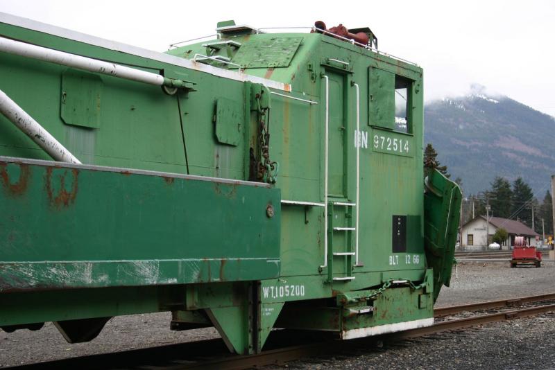
Prototype
(https://farm5.staticflickr.com/4738/38963243421_da81aa76b5.jpg)
(https://farm5.staticflickr.com/4460/37774289096_bfca777261_z.jpg)

Craig, It looks to be about 4’ square judging by both the man in the foreground and coupler face height. Also you need a right angle bend at the outer edge of the face for your support attachment. Could be the view angle, but the 4’ square face area seems to be flat not curve and on a steep angle up from the bottom to create a wedge when in use. But that is my take on the pics. YMMV (https://www.largescalecentral.com/externals/tinymce/plugins/emoticons/img/smiley-cool.gif)

Additions are looking great Craig.

Dave,

Thanks. From the pictures I have, the original plow is bent on a curve, and than years later a flat spot was welded over the curved piece. Let me play around and get some other pictures.

Anyone else ever get the the point of frustration that you just want to pick up your model and throw it as hard as as fast as you can against a solid object, utterly destroying the modeling work of the last 4 years?

I’m about there. Today, when I was sanding and smoothing out yet another part, my slide glass window decided it need to form a major crack. Now I have to completely rip out a whole section to replace this window, and start the process of sanding again.

Along with some other minor compounding errors (the frame goes from 8’ 8" down to 7’ 11", thus off square), and early mistakes are causing me to really rethink the sanity of this project.

Anyone want to help shove this model into the abyss?

Craig

Craig, Dollars to donuts all modelers have achieved that level of frustration at a few points in time. Join that club now. Set the model on the back of the work area and work on a totally different type of project. Come back in a week or two and repair what is wrong (https://www.largescalecentral.com/externals/tinymce/plugins/emoticons/img/smiley-cool.gif)

Don’t throw it, the relief is only momentary and then you realize all is lost. You know how I know …(https://www.largescalecentral.com/externals/tinymce/plugins/emoticons/img/smiley-undecided.gif)

Craig Townsend said:

Anyone else ever get the the point of frustration that you just want to pick up your model and throw it as hard as as fast as you can against a solid object, utterly destroying the modeling work of the last 4 years?

I’m about there. Today, when I was sanding and smoothing out yet another part, my slide glass window decided it need to form a major crack. Now I have to completely rip out a whole section to replace this window, and start the process of sanding again.

Along with some other minor compounding errors (the frame goes from 8’ 8" down to 7’ 11", thus off square), and early mistakes are causing me to really rethink the sanity of this project.

Anyone want to help shove this model into the abyss?

Craig

BY God the horror of the thought !!! You are off a whole scale foot!

This post has been edited by Rooster:conversations with Craig are now just setting in?

Actually Rooster, its 9" scale… And yes it does make a difference when you are making a box. It goes from being a rectangle to a parallagram.

In all honesty, I should have spent the time drawing this up in a CAD program and had the major body parts laser cut. My next scratch build (Thrall All Door Boxcar) will use that process.