Greg Elmassian said:
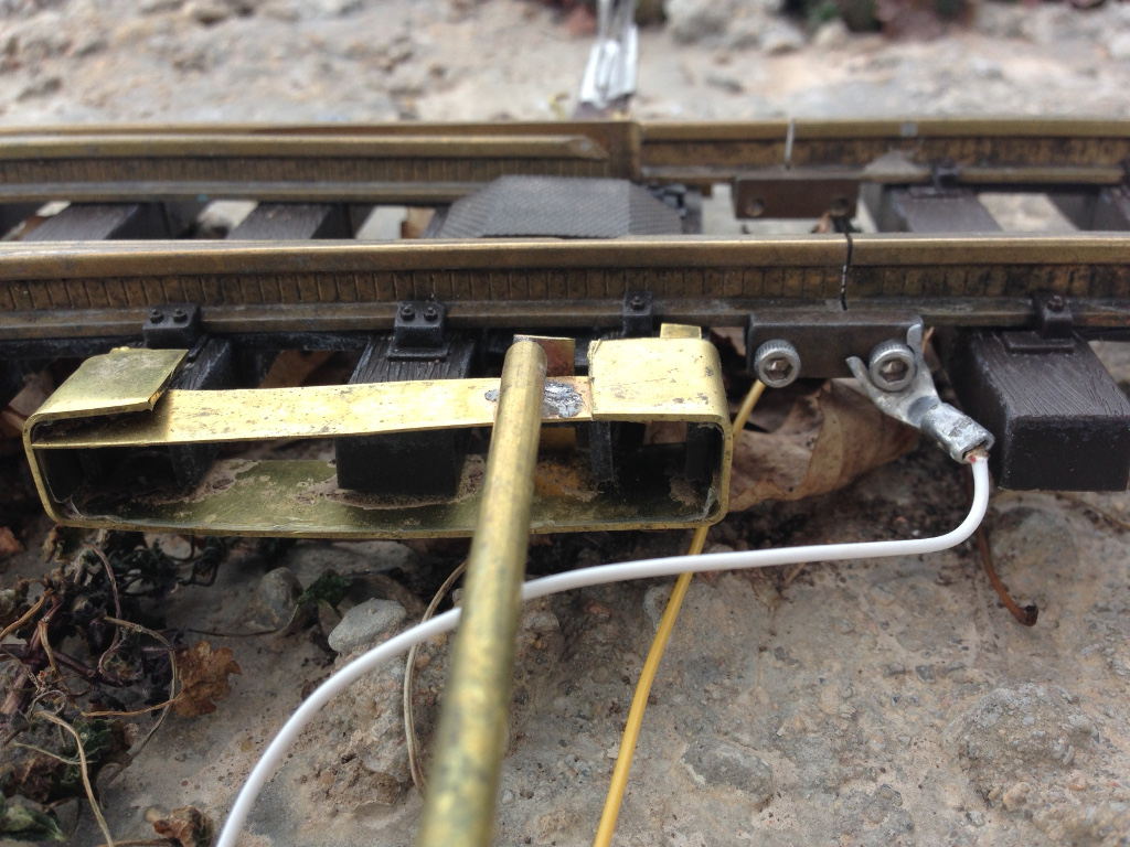
I took a look on your site Dan, could you give some closeups of the “clip” showing how it attaches to the switch and tube?
Also, did you put plasticdip over the pushbuttons? How do they move if covered with plasticdip?
Thanks, Greg
Hi Greg,
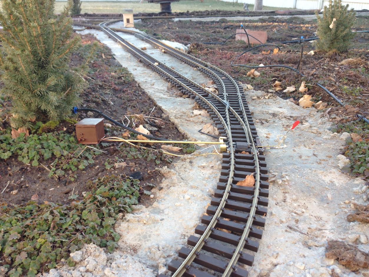
As you guessed, the whole thing is powered from the track. I have two wires running alongside the tube between the box that houses the singlet and the switch. The wires attach on the switch end with soldered-on ring connectors in split-jaw rail clamps. So power and signal are over those two wires. It’s pretty convenient, because it means no additional wiring/pneumatics/whatever to the switch locations. That’s the main reason I’m trying this…
As for construction, I’ll grab some photos of it this afternoon as that would be better than a description… the “clip” is hard to explain. There’s a flat piece of brass stock soldered to the tube. It has pins in the bottom of it that go into the screw holes in the tops of the ties. Then there’s a brass “loop” that goes around the whole thing (stock and ties) that holds the brass piece down so the pins don’t come out. This keeps the whole thing together, but makes it really easy to remove if something goes wrong. Like I said, a picture would be better.
The waterproofing was done by dipping the servo and singlet–I held the singlet by the servo connectors so they (and the screw terminals) were above the plastidip. Both of them are pretty much completely coated. The singlet fascia controller I dipped the back and did the “front” with a paintbrush. I painted right over the push button housings, though not all the way up the plastic posts. The plastidip is flexible enough (or the switches sensitive enough) that they still work–although they’re stiff. I don’t expect to use the switches much (and probably never in the one installed location–it’s out in the middle of the layout) so I wasn’t too worried even if they had stopped working.
