Howdy
A while ago I ran across a webpage or something that had the math involved for making overthrow springs for switches, to keep the points pressed up against the rails. Of course, now that I want it, I cant find it. Anyone help me out?
I didn’t realize there was math involved, I thought it was just a reorganized paper clip that you kept bending till it worked the way you wanted 
I use very small stainless steel wire with a ‘Z’ bend. No math or layouts involved. If I don’t like what I made, I either re-bend it or toss it and start over.
Large paper clips are too rigid and the smaller ones rust.
Happy RRing,
Jerry
I just use a simple “V” shaped spring. The only math involved is that the width of the top of the V has to be wider than the distance between the holes you drill in the throwbar and the nearest tie. The location of these two holes are the only “critical” things, and even that’s pretty non-mathematic. Move the points so they’re between both stock rails, then drill a hole in the throw bar, and another hole in the tie nearest to, the same distance from the rails.
Bend the ends of the “V” spring down, insert into the holes, and voila! Simple spring switch. (Okay, technically called a “rubber” switch since the points just swap over, not return to the original position.)
I think there’s a diagram in my recent GR series on switch maintenance. If there’s not, I think there’s one in the “letters” section an issue or two later.
Later,
K
Is there any trick to where the holes are drilled in the tie, and throw bar? I assume they have to be centered on each other at mid-throw?
Bob McCown said:Yes, they have to be lined up with each other (a line parallel to the rails) at mid-throw, but they do not necessarily have to be in the middle of the tie (midway between both rails).
Is there any trick to where the holes are drilled in the tie, and throw bar? I assume they have to be centered on each other at mid-throw?
Later,
K
Let me see if I understand what you are saying.
I have a loop at both ends of the line I wish for the “Y” (at each end) to work automatically, so I would spring the “Y” to the exiting the loop position and the train would move the switch to entering the loop position?
John
If you’ve got a switch at the close of a reverse loop, and the switch is thrown with a “spring” switch, then the train would enter the loop via the switch set to that direction. When it comes around the loop, the wheels open the points so the train can exit the loop without derailing, but once clear of the switch, the spring closes the switch back to the original position. When the train returned to the loop, it would go through the same direction it did the time before.
On a “rubber” switch, the train moves the points over so not to derail, and they stay there. When the train returns to the loop, it goes around the opposite direction it did the last time.
In both cases, the wheels themselves throw the switch. Pilot wheels are prone to derail on such switches, so care should be taken.
Later,
K
I’ve been using Tom’s safety pin method for a while. Works pretty good once I figured out where to drill the holes and how to bend the clips.
The springs have to push OUT, not pull IN, right?
Yea, make them so you have to compress them to fit in the holes. I use piano wire.
Yes. They push out. Thanks, guys, for the pics. Saves me the trouble. 
Now, does anyone know where I put my ballast brush?
Later,
K
Kevin Strong said:
Now, does anyone know where I put my ballast brush?K
It’s in your back pocket…
You know, I’ve seen those pics before but never fully understood how it was supposed to work, until now! Thanks for explanations, and thanks to Bob for asking the questions that I didn’t know how to ask.
I hear ya Ray. When I wanted to do this a many months ago I had a hard time dragging this information out of anyone. I ended up experimenting with hole placement and bends until I got it to work.
My application is in a R1 switch yard where spacing is too close for the stock Aristo machines. The spring allows the points to be snapped over by fingers when facing the points, or by the wheels when leaving the siding.
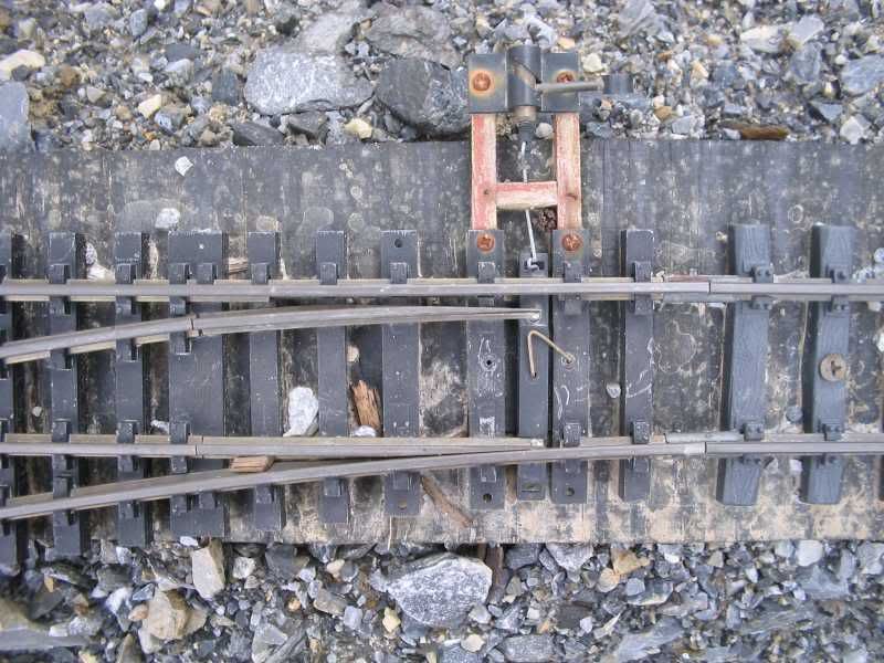
Sorry about dragging up an old thread, but this has pictures and everything. :lol: Heres my problem. My springs look just like Ken’s in his photo.
(http://i253.photobucket.com/albums/hh58/rgseng/rgs009.jpg)
However, the turnout will always return to the straight through position. What I want is what Bob wanted in his original post in this thread, a spring that will keep the points tight against the stock rails. Is this what this design does, always return the points to straight through, or have I missed something? My spring has to be compressed to be installed, just like the destructions say. Whiskey Tango Foxtrot? One other piece of info, my points are not jointed like Aristo’s and others, they are like Rodney’s, though not as elegant.