Large Scale Central

Need a Voltage Regulator to Drop 24VDC to 18VDC

My Frankfort Terminal Railroad will soon be powered by my Meanwell 120VAC to 24VDC power supply. I need to drop the 24VDC to 18VDC to feed my olde tyme Train Engineer control unit. I have been using a string of diodes to drop the power for testing but I would like to use something more compact for the final installation. Is there a Voltage Regulator that would work to drop the 24VDC to 18VDC? I am running some reasonably low amp draw engines such as a Kalamazoo 4-4-0 and a Hartland 0-4-0.

Thanks,

Does the Meanwell have a trim pot to inside to adjust the output voltage? If so, you might get lucky and be able to drop it the 6 volts you need. I had a 12V Ham Radio supply that I was able to boost to about 16 volts using the trim pot.

Failing that, there are simple regulators out there. someone else can probably point you to thw right part numbers and a circuit.

David Palmeter said:

My Frankfort Terminal Railroad will soon be powered by my Meanwell 120VAC to 24VDC power supply. I need to drop the 24VDC to 18VDC to feed my olde tyme Train Engineer control unit. I have been using a string of diodes to drop the power for testing but I would like to use something more compact for the final installation. Is there a Voltage Regulator that would work to drop the 24VDC to 18VDC? I am running some reasonably low amp draw engines such as a Kalamazoo 4-4-0 and a Hartland 0-4-0.

Thanks,

David - you may want to use something like this:

http://www.ebay.com/itm/DC-8-40V-to-1-25-36V-Buck-Converter-Step-Down-Car-Power-Supply-Voltage-Regulator-/131216510357?pt=LH_DefaultDomain_0&hash=item1e8d1d0d95

These devices are much more efficient than voltage regulators and don’t heat up nearly as much. I have had good luck with them— if you only need a few amps this should work, too, for less $$$$$

http://www.ebay.com/itm/DC-Buck-Step-Down-Converter-DC-5A-Regulator-Voltage-Current-Adjustable-YG-/111362310695?pt=LH_DefaultDomain_0&hash=item19edb60227

These are also available from Amazon:

http://www.amazon.com/s/ref=nb_sb_noss?url=search-alias%3Daps&field-keywords=DC%20Buck%20Step%20Down%20Converter%20DC

dave

@ Both Davids,

My club, has since I joined about 7 years ago, been running Train Engineers on 24 volt Meanwell power supplies. I have one I set up to be portable and it works like a champ. Generally speaking, but the time you get out of the power supply, the smallest load will drop the voltage to about 20, and then through the TE is another bit. I have run everything from a Hartland MAC, to USAT diesels, Bachmann whatever I own with no ill affects. I have never really run at full voltage on the TE anyway, I run trains not rockets. :slight_smile:

My tuppence worth.

Bob C

David Palmeter said:

My Frankfort Terminal Railroad will soon be powered by my Meanwell 120VAC to 24VDC power supply. I need to drop the 24VDC to 18VDC to feed my “olde tyme” Train Engineer control unit.

Thanks,

How old is olde? If it is one of the black 10 amp units, you don’t need to drop the voltage. Furthermore, if you do want to drop the voltage, your Meanwell has a pot to do this, though I don’t think it will go under 20 volts.

The older black 10 amp train engineers pass more voltage than the later ones, and for consistency, I have to turn that Meanwell down almost 2 volts to get the same full output voltage from that TE as my two later TEs also on Meanwells running at about 24 volts. I use three 24 volt, 12.5 amp Meanwells for the three TEs.

I have been running my 27mhz TE on 24 volts for 10 years and have had no problem.

I do have the fans installed and they stay outdoors in an unheated cabinet all year round here in New England where the temp goes down to -20F and up to 100F with 100 per cent humidity.

Also I use the 55475 but run these from the older Ultima at 21 volts no load.

I would not run the metal cased unit higher than 21 volts, and it wold never go over 4 amps and then it had a high voltage drop.

Thanks folks, I am learning a lot. I just need to confess that, as a mechanical engineer, I have never trusted working on things I can’t see, so I don’t experiment much with projects that are reported to have electrons bouncing around inside. My EE prof always got a chuckle out of watching us ME’s trying to chase those little electronical things.

Back to the topic at hand:

Yes, Jon, the Meanwell has a trim pot that I carefully left alone (see above), so I decided to see what it does and sure enough, it adjusts the output from 27.8VDC down to 22VDC, no load.

David, the regulators you pointed out look affordable enough for messing around so the pair of Amazons are on the way.

Bob, it is tempting to go naked but for the pittance David mentioned, I think protection makes sense.

Todd – okay, you aked for it, now you get to watch my incredible video of the first test of the MW – diode pile – olde TE setup so you can see how olde it is:

Dan, as show in the amazing video above, I do have a fan in the Meanwell housing and I will have two fans in the enclosure for the 2 TE’s. I hope that handles the heat.

Thanks to all for your responses!

Well, the video was there in the preview, but the electrons ate it. Let’s try this:

https://www.youtube.com/watch?v=geSMaM3byjo

The TE needs the fan installed on top of the unit to force air through it.

Inside there is a 2 pin connector and that is tied to a 12 volt regulator.

I have used 12 volt fans I removed from computer towers in many TE’s.

Aristo documents stated 5 amps or more needed these fans but the Aristo forum had a statement from Lewis suggesting over 3 amps they need to be added.

David Palmeter said:

Thanks folks, I am learning a lot. I just need to confess that, as a mechanical engineer, I have never trusted working on things I can’t see, so I don’t experiment much with projects that are reported to have electrons bouncing around inside. My EE prof always got a chuckle out of watching us ME’s trying to chase those little electronical things.

Back to the topic at hand:

Yes, Jon, the Meanwell has a trim pot that I carefully left alone (see above), so I decided to see what it does and sure enough, it adjusts the output from 27.8VDC down to 22VDC, no load.

David, the regulators you pointed out look affordable enough for messing around so the pair of Amazons are on the way.

Bob, it is tempting to go naked but for the pittance David mentioned, I think protection makes sense.

Todd – okay, you aked for it, now you get to watch my incredible video of the first test of the MW – diode pile – olde TE setup so you can see how olde it is:

Dan, as show in the amazing video above, I do have a fan in the Meanwell housing and I will have two fans in the enclosure for the 2 TE’s. I hope that handles the heat.

Thanks to all for your responses!
David - while you are awaiting delivery from Amazon you may want to look over these two articles about their use —

dave

http://www.trainelectronics.com/artcles/DC-DC_Converter/SwitchMode.htm

http://www.trainelectronics.com/artcles/DC-DC_Converter/index.htm

Since this topic seems to have been answered, I’d like to ask a question on Aristo trackside TE’s.

From what I know, there was an early “basic” TE, only one channel.

Then there was the metal cased one, which handles 4 amps.

Then come the plastic cased ones… I believe the early ones had a linear/pwc switch.

Is this right so far? I’m mainly asking Dave and Dan, but anyone with knowledge is really being asked.

I’m trying to complete an informative web page, and most importantly, the way for people to clearly identify the different versions.

Also, after all this is clear, which are the ones that can run at the higher input voltage?

Thanks, Greg

I’m by no means an authority on the TE, but I’ve owned a few of the later 10 Channel 10A units. These are the ones in the plastic case with an optional fan. They came in several versions. I think they all have the Linear/PWC switch on the base. The transmitters are different. IIRC, the early ones had an On/Off button, and the later ones had an auto power-off feature and no button. There also were two different antennas; a rubber duck and a chrome extendable rod.

EDIT to add: The firmware differs on some as well in regards to the direction buttons. Original firmware had two distinct direction buttons. Later firmware either button would change direction from current. That was a George S. suggestion and I really hated it - No way to know for sure which way a stopped engine was going to move when you accelerate.

On my early 10 amp unit (black pancake style with fan), the transmitter has two "TRACK CHANNEL"s. There are FAST, SLOW, <—, —>, and EMERGENCY STOP as push buttons, just like on my four later transmitters. The five membrane switches are arranged like a 5-spot on a die labeled A-E. The receiver looks identical to the later receivers with a switch for linear and pulse width. The speed steps are much cruder than the later units and it tends to drift more with no load. But is does pass more voltage than the later units.

My three later TE transmitters as well as the one for my 27-mHz in-cab radio receiver (for battery power) have the same push buttons. Below are 9 membrane switches labeled A - F in the first two rows and the row at the bottom is labeled SPD DIR FRQ.

There are also two small buttons toward the top below the LED “window” to change the “TRACK/TRAIN/RF-CH” labeled from 1 to 0.

These trackside units also have the switchable linear/pulse width switch. Even these later units represent a couple generations and one generation has an unreasonably long momentum even at its lowest setting.

The telescopic antennae work better than the rubber ducks and I’ve replaced them where applicable. I also use a CB antenna attached to the receivers. (CB operates in the same portion of the spectrum.)

Note that there were 2 different 2 channel (Track 1 and 2) transmitters and receivers.

One was made in Korea. I have had both and they are not identical!!

So, more info for Greg.

The Basic (27mhz orange transmitter 9 volt battery) and orange 2.5 amp receiver are not digital and any 27mhz transmitters (read CB radios or any other 27 mhz toy transmitters) will interfere with the operation of this unit.

Then the metal cased ‘4 amp’ 2 track receiver and 2 track black transmitter. Mine would only do a little over 3 amps and then the voltage output started dropping real fast.

The real 10 amp (10 track 10 frequency) came out but needed a fan for full output, plus rating in linear mode was 8 amp.

One version had an external terminal for a 12 volt fan.

And transmitters had 3 versions as mentioned above.

All 27 mhz transmitters were black.

Then there was the 75 mhz unit mdeled after the 27mhz, transmiotters were grey.

2 models made, HO had a built in magnet on the bottom for resetting the on board receiver. G model was identical in operation but did not have the magnet. 2 different on board receivers were made, 3 amp G and a smaller HO version. G version could have a relay board added to control smoke, lights, etc.

Also note that the original 2 track receiver could have a 5 function add-on (round din connector) and I have seen these still available from Star hobby. The a-e keys enable the outputs. Some users used this unit on board with the receiver and had control of lights/sound.

THe 10 channel units had the 55474 and 55475 receivers with controls for pulsed switch controls (LGB EPL or early Aristo units)

Note that George Schreyer wrote a great manual on these products and was sold via Aristo on all but the latest 27 mhz (Transmitter with on-off button)

I might have George’s book around here somewhere if I didn’t give it away when I sold off my TE units.

Thanks guys!

I’ve updated my page, hope I got it right… quite a history there:

http://elmassian.com/trains/dcc-battery-rc-electronics/battery-power-remote-control/aristo-rc/27-mhz-train-engineer

Regards, Greg

Hi Folks,

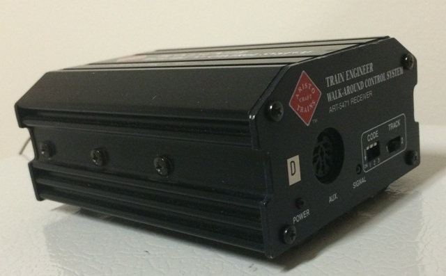
Just as I am finishing my comprehensive wiring as noted in my original post above, one of the Aristocraft ART-5471 receivers fell ill. I am using two of them with the new wiring and one is working fine and staying cool while providing power all the way out to the test train. The other identical one, pictured below, with 18 vdc input applied is only showing about 0.6 vdc output. It is, however, getting very hot; the ‘Power’ and ‘Signal’ indicators are working properly. It has worked fine for the past two years with my temporary wiring. They both were bought used from a friend.

ART-5471

Anyone have an idea about what the problem could be? I have not taken the unit apart, but I am willing.

Happy Thanksgiving to all,

David

The screws on the outside hold transistors to the case as the metal case is a heat sink.

There is a 10 amp fuse inside this unit which rarely fails as the unit could never draw more than 4 amps which I assume is a limit of the transistors used.

So, I would check the fuse first and if bad, replace with 10 amp and then add a 4 amp fuse to the output of this unit if and when it starts working again.