Some of you are aware that, for some time, I’ve been messing with designs for a more robust electric-op switch machine. Inspired by Dave Bodnar’s custom-made boards, about a year ago I turned up the heat on the project. I did the 3D design work in Solidworks and the 2D schematic in Autocad (actually I switched to BricsCad, but that’s another story).
Anyway, the road to getting a circuit board made from mechanical design software has been perplexing, because the board manufacturers take “Gerber” (or similar) design files that are generated by electronics software and those folks that are into that. I’m not electronically proficient, nor do I want to spend gobs of money for specialized software. So, to cut to the chase, here’s the process I’ve gradually settled on.
The 3D design, and all “trace” routing, was done in Solidworks. Blue lines are top traces, red are on the bottom. You don’t need to use 3D CAD, 2D is fine; but this is how I wanted to do it, because the packaging is so tight.
.jpg)
Here’s just the board.
.jpg)
The linework for the board’s outline, holes and traces was exported in a couple views (to keep the top and bottom traces separate. Here’s one of them.
.jpg)
After that came the 2D CAD, using a (very good, but vastly cheaper) Acad clone. I moved things to the proper layers, added text, etc. Reversed gray text will be printed on the bottom side.
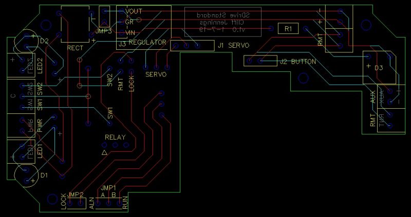
This was exported to DXF format (which looks the same), to get sucked into the sparky software. It took quite a while to get the CAD layer names right, so that they were honored in the next phase. But once that was straightened out, along with a bunch of other misc settings, the import to DesignSpark has gotten very fast. The image below is exactly how it was imported, with the exception of all the round “pads” which had to be manually placed (not very hard though).
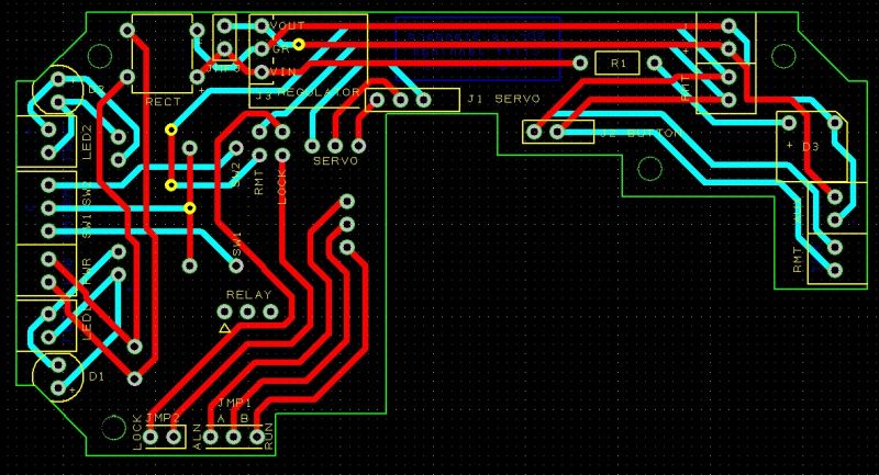
DesignSpark offers many products, including this PCB software; and it’s 100% free. This was the key step for me to translate the CAD layers into the “Gerber” or whatever numeric language that PCB manufacturers require. So the last step (and I’ve been trial-and-erroring this all day, but It’s now working great) is to output those files. These files represent all the layers involved, with this list being an example:
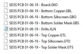
These names are NOT how DS exports them, but how the next step requires them to be named. So after renaming to what you see, the files were zipped into 1 zip file and uploaded to the manufacturer’s site. In this case, and at the advice of Dave Bodnar and others, I’m using Osh Park (Oshpark.com). Again, it took some fiddling around, but the great thing about OP is that they show you how each layer (outline, holes, copper, mask, silkscreen) will turn out before you put the order in. Eventually, all looked ok.
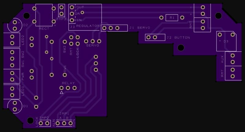
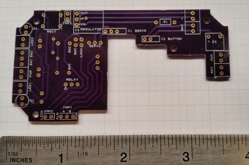
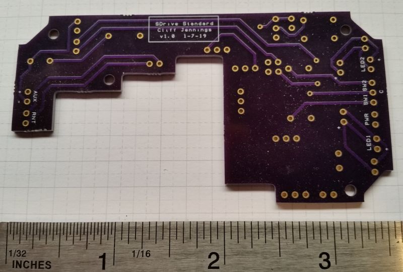
Their prototype service is $5 / sq inch for 3 boards. So, for $35, I’ll get 3 of these to check out. The ultimate objective will be a bunch of these:
.jpg)
Cheers,
===>Cliffy
