Large Scale Central

Module Legs on the VGRS

Don or Bob,

I am very intrigued by the VGRS’s module legs, looking at the pictures posted by Don in Craig Townsend’s posting about a raised semi temporary layout. I used electrical conduit pipe and screw the legs in to pipe couplings on my Time saver. I am not happy with the stability results of my modules. Does the PVC legs on the VGRS modules screw in or just socket fit in to those wood blocks in each corner of the modules?

From our VGRS.US module guru:

the legs are 1 1/2" PVC as opposed to the 1" ones Bob and John have on their modules.

There is a wooden block with a 1 1/2" PVC coupling fitted snuggly in it and screws hold it in place.

The larger pvc is much more stable than the shaky 1" stuff. The 4 modules together are very stable.

Don, Those are just end caps, screwed to the table bottom, right???

Looks like it dad

Coupling.

Like this at Lowes

(http://images.lowes.com/product/converted/611942/611942031894.jpg)

Hole for the outside diameter was drilled into the corner block.

Then the little ridge inside was removed if I remember correctly.

Then the coupling was screwed to the block from inside the coupling making sure the screwheads were below the inner coupling surface so the leg has the benefit of the full length of the coupling.

Then the corner block is attached to the frame.

The bottom of the leg has something, probably an end cap, that then has mounted in the end cap an adjustable foot.

Entire VGRS Timesaver album:

https://picasaweb.google.com/vtgrsociety/TimesaverProject?authkey=Gv1sRgCMnCqcaCt8P61wE&feat=email

So they are just a socket fit, no screw threads? Do they ever get stuck or wedged, so tight, they are difficult to get apart? So I’m guessing those blocks are about 2 inches thick? As I said, very interesting. Now, I just need some ambition. Hard to find these days. Thanks for posting.

Don,

The picture you posted showing the bottom of the leg with a level adjuster, seems to suggest the coupler socket for the legs were also mounted at a slight angle. Maybe 5 degrees or so. Is this the case, or are the legs mounted plumb ?

Dave,

Good eye. I would think a slight angle out at the bottom toward the corner would give a lot of stability. I’m sure the blocks is better than my original attachment.

On our Timesaver modules, I mounted the screw in sockets under the modules plumb with the bottom and sides. Now I just glued and screwed them in to the frame and I was amazed at how woobley they were.

Don and Bob looked the Timesaver over at York, before they started construction. One of the things we discussed was that lack of stability. Working on the idea of a refit. Not really interested in adding weight, but I’d like to upgrade.

One additional requirement we have is a need for multiple heights and setting up as part of our home railroad on a shelf. So we can’t having anything protruding past the frame edge of the modules.

Dave,

Sorry I missed your query. I’ll discuss with the builder, although I think he did NOT design in an angle. The wooden block the leg fits in was drilled by eye. There is enough wiggle room to have the leg show a slight angle when at the floor level, AND I took the picture from a funny angle, too. I do not recall any of the legs actually splaying out, as they would interfere with adjoining modules and presumed human foot space. These 4 modules assemble into a long straight that can then become part of an oval module setup. More detail later when I get the answer from the builder.

Don,

Didn’t you send me a picture of all the modules, together. Maybe that picture would show the cantered angle.

Ric and Dave:

See the album link in my post towards the top, and pasted again, below

https://picasaweb.google.com/vtgrsociety/TimesaverProject?authkey=Gv1sRgCMnCqcaCt8P61wE&feat=email

Don,

Thanks for the link. From looking at the pics it seems the legs are plumb from the table and the one pic of the adjustable foot shows the wiggle room you mention above.

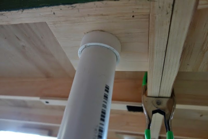
That said, and understanding the need to keep all pieces within the confines of the table top, there is no reason the upper blocks couldn’t be mounted 3"(or more) in from each edge and then drilled at a 5 degree cant to give a slight angle to the legs while keeping the foot inside the confines of the top.

This would increase the stability of the narrow table while keeping the legs out of foot traffic reach. IMHO The more industrious designers would drill so the 5 degree cant angled the leg both to the side and the edge.

This could also be done on the time saver, Ric, with a shim under the threaded ring, if you don’t want to change the whole design.

To add, that the adjustable foot is a really good improvement for using on any table that needs to be set up in multiple areas.

On the HO modules in my clubs, they are quite wobbly by themselves, but when joined together into a layout, the whole assemblage becomes rather ridged. .Yes, if one end is body checked, the whole thing will move, but it doesn’t sit there and sway back and fourth.