Large Scale Central

Making a drive truck for my rail truck

I figured you guys would like to see and hear the whole sorry saga of this railtruck. The quest for a power truck was covered in a separate thread, and I decided to make my own so here goes.

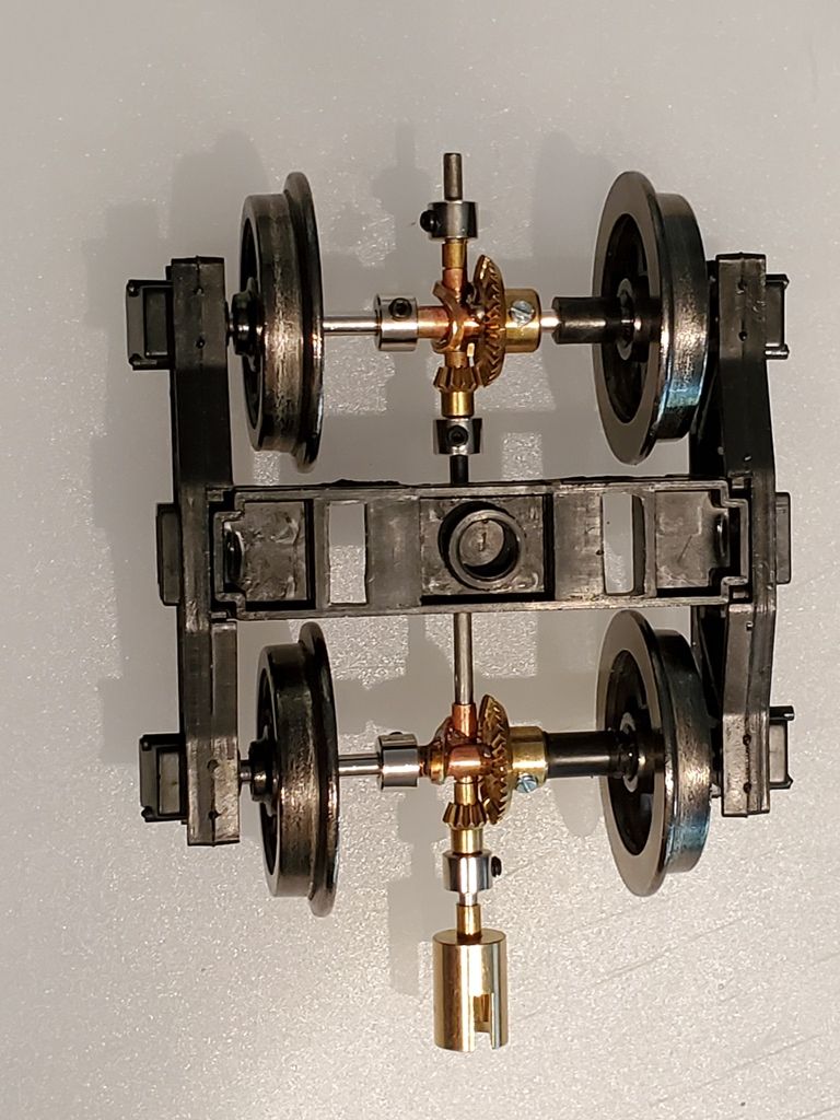
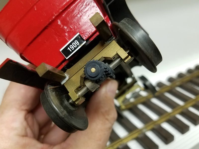
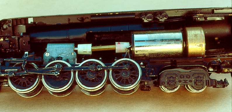
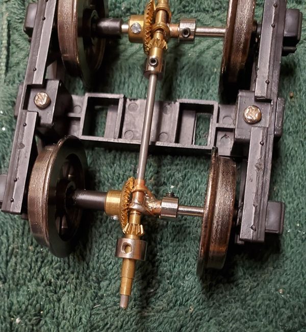
The rear truck has to be set up to drive like the Bachmann railtruck axle - the motor and driveshaft come from the front just like a real truck. The present truck is an archbar with solid wheels, and I figured spoked wheels would look better. I also decided to use my skew bevels that I got from eBay (Tradeship, old slot car parts.)

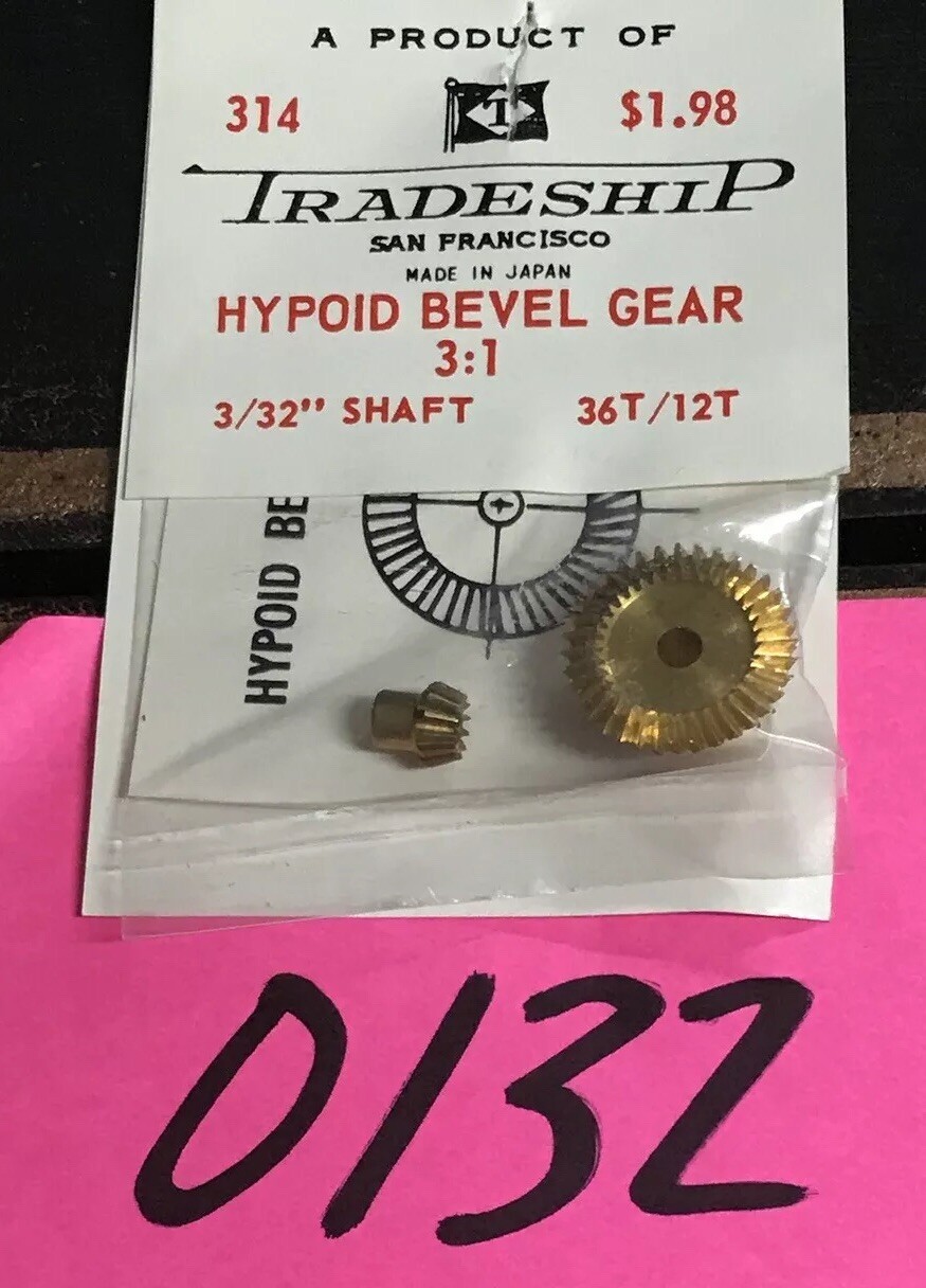
So I started accumulating bits and pieces. I found a pair of spoked Liliput (Bachmann Europe) wheels and a pair of Bachmann small wheels in my parts box. The axle for the latter is 3mm which is 0.118", somewhere between 3/32 and 1/8th (0.125"). The bevels say 3/32 shaft on the package.

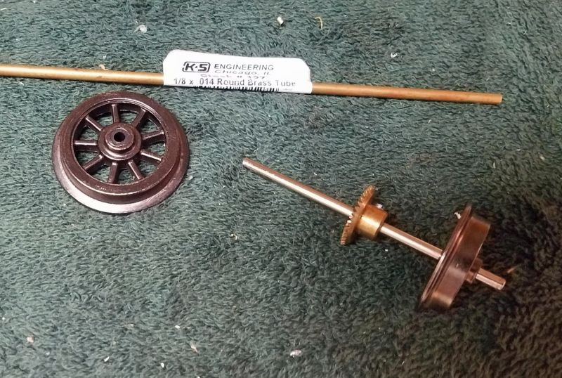
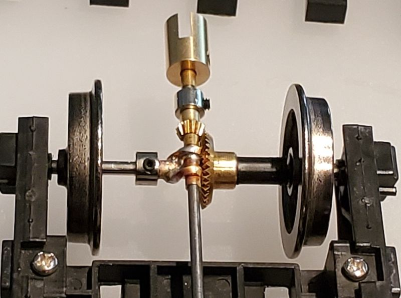
I found some 1/8" brass tube, and I took a wheel off the spoked and the small wheel pairs. Turned out the Liliput used a sholdered axle, so the 3mm axle off the small wheels would have to work. I found a 3mm drill and prepared to open up the 3/32" (0.093") shaft in the large bevel, only to find it was 1/8" ! As you can see above, it fits the shaft, and the difference in size is only 0.007 (7 thou.) However, the set screw is only on one side, so the bevel won’t be centered if I don’t shim it.

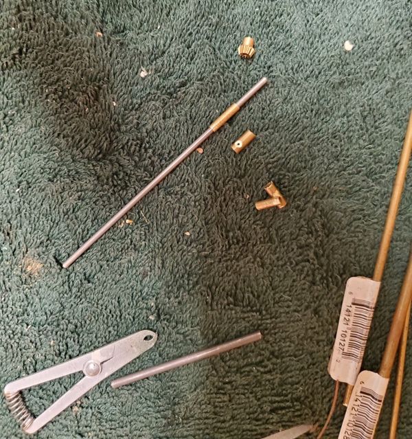
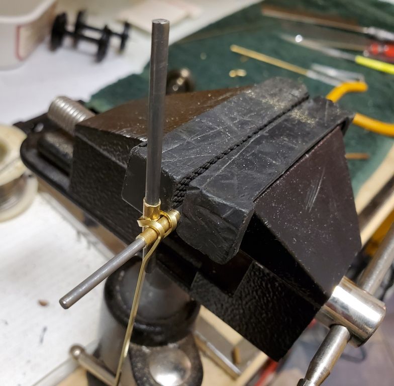
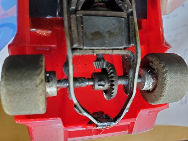
Next is to find some 3/32 steel rod to use as the drive shaft across the axles. I’ll probably need a universal or 2 that fit the same shaft. And some 1/8" inside bore tube to use on the axle to support the drive shaft. I plan on soldering a “crossbox” as Grandt Line calls them. There was one on my Railcar that I just fixed, which gave me the idea.

I’m hoping for an enjoyable and educational, not sad, saga here so I can think about building my own railtruck. Go Pete go!

Jim, Try this for your axles https://www.mcmaster.com/8893k133

Following with great anticipation, Pete. Thanks for sharing your process.

Pete,

Here’s hoping for success! Selfishly, here’s hoping that I can follow parts of your path to breathe life back into Charlie, Oldest Son’s B’mann railtruck.

Eric

Bob Cope said:

Jim, Try this for your axles https://www.mcmaster.com/8893k133

Bob, thanks for the link. The axles are 1/8th so the 3mm Bachmann axles will do, with a shim if necessary. Star Hobby had 3/32 steel rod so I am all set for the drive shaft.

I ordered some 3/32 collars with set screws from Tower Hobby, and a 1/8 shaft universal. Google couldn’t find me a 3/32 shaft universal. I think the current railtruck motor has 1/2 the original universal so I can probably make something to fit.

It is possible this truck never had the gearbox fixed. I may have to tear it down to check.

Eric Mueller said:

Pete,

Here’s hoping for success! Selfishly, here’s hoping that I can follow parts of your path to breathe life back into Charlie, Oldest Son’s B’mann railtruck.

Eric

It seems unlikely that my approach will help a std railtruck. Check George Schreyers pages for insight into the gear problems.

P.S. I was offered a complete railtruck that (maybe) just needs some wires soldered for $75. PM me if you want his email.

I had some time yesterday to work on the truck and here’s the current progress:

To backtrack, the skew bevels advertised they were about 1/8th inch skewed (the cross shaft 1/8th in above the main shaft.) I’m using a 3mm (1/8th) axle which fits 5/32 brass tube, and a 3/32 in drive shaft which fits in a 1/8th in tube.

I cut some pieces of tube, trying to get them flat at the ends - I even got out the table saw at one point. Between dropping them on the floor and having them fall into the saw I made twice as many as I needed! In theory, a 1/8th tube on a 1/8th axle should place the cross-shaft 1/8th inch above the axle, center-to-center. I initially filed a depression in the 5/32 axle shaft tube to locate the cross-shaft tube. It didn’t look as if the gears were happy at that spacing, so I filed a depression down to the shaft on each one with a curved file.

As you probably figured, I’m making a crossbox like the one on my railcar:

I would have bought one or two, but Grandt Line seems to be out of business.

Anyway, I was wondering how to hold it all in place for soldering, and found some 1/32 x 1/16 brass strip in my stash, which folded nicely around the tubes and shafts:

You can see the end result of the soldering using a small gas torch:

The underside, when I finished fitting the collars to hold the gears in place. The gears mesh but seem finicky - maybe not perfectly 1/8th inch skewed ,and maybe needing to be run in.

Not sure how I am going to get at the truck pivot!

The big brass collar on the end of the drive shaft is a universal that I bought from Tower Hobbies - it’s designed for a boat and 1/8th shaft. I sleeved the shaft with some more 1/8th tube, but it is not a good solution. I need to find some O-scale universal joints, as I haven’t found any in large scale.

A few additional comments about the Bachmann railtruck and other gear issues.

The back axle on the original truck is almost a 1:1 gear - there’s a bevel and some spurs, clearly visible in the B’mann parts store or diagrams. The worm gear is at the other end, so the reduction gearing is under the hood. If the motor was a direct drive, one could use a couple of worm gear towers like this one:

Given that it is 1:1, and that skew bevel gears are not very common, you could rebuild the B’mann single axle railtruck with slot car gears like these: (50-year-old 1/32nd slot car, 3:1 gears but 2:1 available, and lower ratios.) Note the U bracket holding the axle to the motor.

You might put some toothpaste on the gears, and run them a bit and then clean off and look at the wear pattern, that might be informative, and also might “wear in” the gears.

Greg

Greg Elmassian said:

You might put some toothpaste on the gears, and run them a bit and then clean off and look at the wear pattern, that might be informative, and also might “wear in” the gears.

Actually, we used to wear in the slot car gears with Brasso! I am thinking of attaching a 12V motor/drill to the drive shaft (pic below) and ‘running it in’ that way.

The small bevel pinions are currently not attached to the drive shaft - that’s another problem to solve. I’d rather they were held with screws like the collars, but I’ve run out of collars so I’ll have to get some more. Then I can make a pin and solder the collar and bevel together.

I took another look at my project after all the postings and noted that I did have some 5/32 in collars, and the small bevel is almost that small. I opened up the collar with an 11/32nd drill which let the gear fit in half the collar. Some 1/8th and 5/32nd tubing sleeved the other end.

I filed a piece to fit against the set screw in the gear, and in the two pieces of tube, and then soldered the gear into the collar. I’ll probably have to solder the tube as well, or maybe leave it and use a 3/32nd collar to hold it all in place.

Some solder ran in to the gear between the teeth which will have to be cleaned out, so on the other one I may try to use the 3/32nd collar and just solder them together.

Thanks for showing all the little ins and outs and problems you are seeing and solving. Very helpful to the rest of us. Keep at it!

This is just the thread I needed to see. I am planning a locomotive build that will require such a drive.

Thanks for the kind words.

It occurred to me that if I could drill the 5/32 collar, I could probably drill the 3/32 collar (both are visible in the above photo.) I didn’t want to solder a butt joint like the one you see on the 3/32 collar at left, as it wouldn’t be very strong. If I drill a short relief passage up to the set screw there will be enough overlap with the pinion gear to make a solid solder joint.

The other issue to be addressed is that the 1/32x1/16 strip bent over the tube is interfering with the large bevel, so I have to move it away and file them down a bit. Then there’s the universal joints to find. There’s a couple of Heisler articles in Steam-in-the-Garden mag that just arrived, and I note the Heisler drive is on the outer axle so the universal is under the truck pivot. No need for a sliding joint. Have to think about that, and about getting a universal from such a model, or a Climax.

Nice work Pete !

Thanks much, Pete. I am really enjoying this build.

Pete,

Have you installed bushings in the truck side frames to take up the typical “play” that you have with plastic trucks?

I just wondered if that axle play (side to side and loose fitting) would interfere with your gear mesh.

Pete, I found this a while back, perhaps some of these universals are the right size?

https://store.rc4wd.com/Punisher-Shafts_c_27.html

Greg

John Bouck said:

Pete,

Have you installed bushings in the truck side frames to take up the typical “play” that you have with plastic trucks?

I just wondered if that axle play (side to side and loose fitting) would interfere with your gear mesh.

John, the sideframes just keep the axles aligned. The brass collars hold the gears in position against the soldered crossbox (brass tubes.) The mesh is adjusted with washers between the tubes and gears. I wanted the whole thing to be loose but with constant mesh.