Large Scale Central

Limiting down-hill speeds?

Hey folks! I’m working on an indoor LGB G Scale layout that’s about 16’ x 9’. It’s an over-under layout. I have a 4% grade to get up and over a trestle then back down 4%. I’m running a LGB Stainz model 2020, with a few cars behind it with track power. In the flat spots and up the grade I have a nice consistent speed, but then on my down-slope, it gets a little fast…well because of gravity. I was under the impression that the Stainz locos were worm-gear driven, so my down hill speed would be somewhat limited. I’m trying to come up with other ideas on limiting the down-hill speeds. So far, I’m considering isolating the downhill slope piece of track and running a separate transformer at a lower voltage, or perhaps wiring that section off the same transformer, but behind some power resistors.

Anyone have any better suggestions?
Nick McBride said:

…or perhaps wiring that section off the same transformer, but behind some power resistors.

Anyone have any better suggestions?

There you go.

Isolate that section of track.

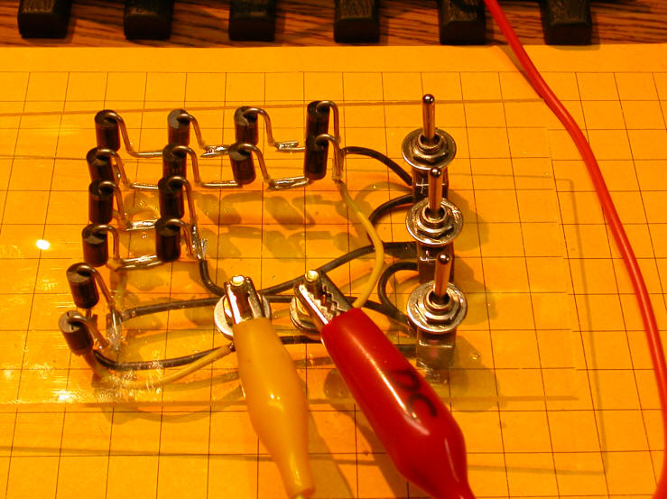
Make up a group of 6 amp diodes (for big trains, but 3 amp would work for a Stanz) with one diode in one direction, wired in parallel with a few diodes wired in series in the other direction. Each diode will drop the voltage by about 0.7 volts. So if you put four diodes in the “series portion” of the group, the trains will experience a 0.7 volt drop when going uphill, but a 2.8 volt drop in the downhill direction.

Put the diode group in the wire between the power pack and the isolated track section. BTW, you only need to isolate one of the two rails at either end over the downhill length, not both. If you find that the trains are now going too slow uphill, but are hardly affected downhill, reverse the diode group in that wire to get the proper orientation.

I used a rheostat to adjust the downhill speed on my N gauge layout years ago. Like Todd said, only one rail was isolated and that rail fed from the same power supply the fed the track, through the rheostat, to control downhill speeds. That way I could adjust the speed for different locos.

If you install a DCC decoder, the engine speed would be more constant even in the DC world.

Other fix would be to add Diodes to the isolated track section, one for going up hill (read reverse) and multiples in series for downhill.

A resistor would really slow down the engine going in reverse uphill as would a second supply. A single diode would not matter much.

Also, the diode method would allow you to run trains in either direction!!!

Thanks for all the great input. Looks like I’m going to go the diode route. I’m assuming that any 6A generic diode rated for at least 50v would be fine? Maybe something like a 6A10?

Nick McBride said:
Thanks for all the great input. Looks like I’m going to go the diode route. I’m assuming that any 6A generic diode rated for at least 50v would be fine? Maybe something like a 6A10?

Nick - you can get away with 3 amp diodes like these from Radio Shack https://www.radioshack.com/products/3-amp-400v-diodes?variant=5717579653

You can get them for much less on eBay (see: http://www.ebay.com/itm/Lot-of-50-NEW-1N5408-3-Amp-1-000-Volt-Rectifier-Diode-3A-1000V-N-O-S-50-Pack-/261727938974?hash=item3cf033699e:g:OF4AAOSw-dBTsyt6 )

There is an article on my web page that goes into a good bit of detail on using these on a project that I built - see:

http://www.trainelectronics.com/artcles/AutomaticBlockSwitchController/Part_3-diodes_speed_control/part_III.htm

You will note that it uses a set of switches so that you can easily adjust the speed decrease.

Good luck with your speed control!

dave

Thanks Dave, that’s a great idea! The write-up is very helpful too. I suppose the next thing I’ll be posting is a picture of my completed speed control. Thanks again for all the great responses.

David Maynard said:

I used a rheostat to adjust the downhill speed on my N gauge layout years ago. Like Todd said, only one rail was isolated and that rail fed from the same power supply the fed the track, through the rheostat, to control downhill speeds. That way I could adjust the speed for different locos.

Nick,

I vividly recall being at the B&O RR Museum garden railway many moons ago when someone arrived with a brand-new USAT J1e Hudson. He got permission to run it on the garden layout and that was fine until it came to the girder bridge flyover. It slowed to a crawl - and I mean a crawl - on the bridge as the downhill track was wired with reduced voltage to prevent runaways, etc.

I strongly suggest you make provision for the fact that all locomotives are different and will react differently to your diodes. Maybe put in a switch or two so that you can adjust the amount of voltage drop?

Pete- the way that I did it (described in the article on my web page) allows you to set three switches to include from 1 to 7 diodes in the power feed ---- It could easily be modified to go to 15 diodes in 1 diode steps.

dave

I use a rotary switch to control my diode speed reduction on my mine point-to-point (three slow down speeds before passing through the station and stopping at the ends). A rotary switch is more intuitive. These handle 10 amps for under $2. Shown are 6 and 4 position, but they have others.

http://www.allelectronics.com/make-a-store/item/rsw-610/6-position-10-amp-rotary-switch/1.html

http://www.allelectronics.com/make-a-store/item/rsw-410/4-position-10-amp-rotary-switch/1.html

Make sure the rotary switch current is at least equal to the power source current or it mat burn the contacts.