Large Scale Central

LiIon Protection Boards - an exploration

Being a cheapskate when it comes to buying something that I can make myself, I’ve spent a couple of years installing Lithium Ion batteries in a few locomotives, using 18650 batteries and battery holders from China. My success has been mixed, to say the least, but the price is right.

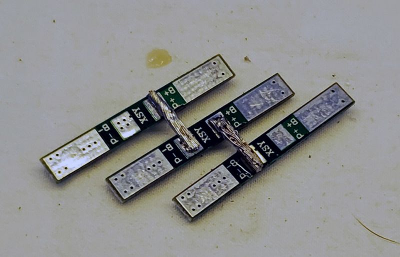
One thing I have found is that the protection boards are very difficult to use. The first one I installed refused to produce any output. The second is still working well. The most recent one was happy to show an output of 12.2V (3 fully charged 18650s at 4.1V each) but dropped to half that when any kind of load was applied. I eventually removed it and built a little array of single cell protection boards and it seems to work fine. Only time will tell.

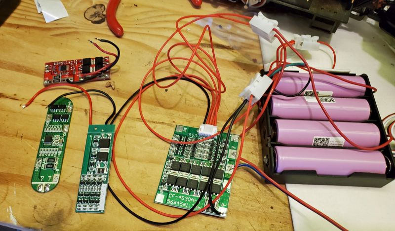
I also have a little LGB Feldbahn with a rig in a trailing gondola with 4 batteries, a receiver, sound card, and throttle/ESC. It worked with the board shown top left on this pic, which is rated 10A, but the loco stopped about halfway round Jack’s track, so I put it on the bench and discovered the protection was cutting power after a few seconds. It clearly needed a new option, so I took the opportunity to pull the battery pack out and experiment with the few types of boards I have in my stash.

The red one came out, and might work in some other application. The one with rounded ends didn’t work at all. The smaller rectangle came out of my little boxcab project and it did the same as I had observed: dropped the voltage output by about 1/2 as soon as it saw any load.

So I dug out the big one - which is rated 30amps. [Mind you, given the skinny wires they supply, I shudder to think what would happen if you pulled 30A from it.] After the test install (shown below, with temporary clips) I saw no sign of problems, so I loaded it all back into the gondola after shortening the wires. It still worked, and this afternoon the train cheerfully chugged around the layout many times with no sign of any problems.

As I have so many duds, I went shopping and found there are now plenty of protection boards for cordless drill battery packs, which are rated 40 amps. I will be trying one of them next.

I will need to find, then read through my pack building notes. Some of these boards have a re-settable cut-off that will trigger if one or more cells is too low, or intermittent, which could happen with your holders. There is a sequence you perform with a load (like a bulb) that will turn the output back on. I found it on the net long ago.

I ran into the need when I was putting batteries in my 2-truck Shay. There was only room for 3 cells in the boiler. I hid a fourth in the air tank. I built and tested the pack outside the loco, then disconnected the external cell so it could be mounted in the tank. When I connected it all back together it would not function. That’s when I learned about the reset capability of the cut-off.

BTW - I buy cells with spot welded solder tabs. I’ve not yet heat damaged any cells while soldering wires or buss bar to the tabs. I do use a rather large soldering heat sink between the battery and the soldering point.

Pete,

I’d take a hard look at the cells to eliminate the most common problem. Each PCB has its specification among other things for current draw and drop out voltage. It’s highly unlikely the battery can give up 10A at rated voltage at the least. It’s plausible one or more cells suffers from voltage degradation under load and is triggering the PCB voltage failsafe specification. As I noted not all boards are created equal, electrical losses combined with variable parameter thresholds mat tell the tale.

Michael

Pete I want you to continue to have fun running trains. You are scaring me with this story. As a reseller of lithium packs that are made by a certified assembler, MTO Battery, this is not a safe practice. I know first hand what a melt down of a lithium cell can do to your skin after trying a cheaper option. You do not get the safe consistent quality of a properly made pack.

I asked MTO Battery to comment: " The bottom line is that the PCM has to be rated to protect the cells. If the cells are only capable of discharging at 7A and you hook a 30A BMS up them you will likely have to draw 60-70A to get it into protection mode. By that time the cells have exploded and/or your wires and connectors have melted. The PCM should be thought of and used as a fuse. If the rating is not correct it is almost pointless to even have it in place".

I am suggesting that you call Jason Able at MTO to get some advice for your battery pack. 717-751-2705

Don

Thanks for the advice guys, I’ll have to confirm that all the cells are showing rated voltage when the pcb cuts me off. However, if that were the case, then none of the boards would work, as they’d all detect under-voltage and cut off?

Don, I am only using these home-made concoctions in low-power situations, and I am not expecting to pull more than an amp or 2. They are really there for over/under-voltage control. You do make a good case for including a 3amp polyfuse in each situation.

I too am a cheapskate, but rather than using battery holders I solder and shrink wrap my own battery packs: either 4-cell or 5-cell, depending on the locomotive. Managed to buy really cheap but good quality batteries from LiIon Warehouse in Phoenixville, PA. Since the specific 16.8V or 21V. chargers already have overcharge protection, the issue is at the discharge end. This I resolve by installing a mini voltmeter on all my locomotives. The rule of thumb is don’t let the pack go down past 3V per cell, i.e. 12V for a 4-cell or 15V for a 5-cell. Yesterday I test ran my 5-cell RS-3 for about three hours, going up to 80% for speed test, but for the most part at slow speed (25%). My battery pack went down from 20.5V to 19.5. In other words, still have a lot of juice left before I need to recharge at 15V.

I also have installed a mini on-off switch for each voltmeter. Alternately, you can use your charge jack to monitor onboard voltage with an external mini voltmeter wired with a charge plug.

That may work for you, but you risk thermal runaway if the pack gets shorted, A protection board would shut the pack down once draw exceeds the threshold. In your case, a short on the battery side of any fuse would cause the pack to get very hot and possibly start on fire. I would not reccomend this to anyone.

I certainly appreciate your point, Jon. Not sure how there could ever be a short in my battery packs. My packs are held together with battery pack brackets, which keep the cells separated and also provide additional protection (channels) for the connectors between cells. Those I triple check to be sure they’re soldered securely. But even if a connector were to come undone, it is prevented from traveling to another cell by the bracket. And then it’s all double shrunk wrapped tight. What am I missing? Happy to learn from your experience. Is eventual corrosion an issue?

https://www.amazon.com/Lithium-Battery-Plastic-Bracket-Cylindrical/dp/B08JHMFVFC/ref=sr_1_17?dchild=1&keywords=18650+battery+pack+holder&qid=1606008321&sr=8-17

Jon,

A properly sized fuse will shut down the power source once the current draw exceeds the fuse rating. In these circumstance I would limit the fuse size to the “NEED”, verses the batteries capability. This is what I’ve been doing for years with Li-ion/Li-Poly batteries I use in my trains, cars, plane and drones. I only charge with a balance charger…

PCB’s do not disconnect the cells from one another, they can only drop the power source from the load.

Thermal Runaway in Lithium-ion batteries is realized when the polyethylene separator ruptures between the cathode and anode. When the separator ruptures, a short circuit occurs which initiates thermal runaway. Thermal runaway is typical of over charging. Other sources are an internal cell short (no stopping until cell failure) or an external electrical short (fuse or PCB disconnects power/short). The short can develop into a high current discharge, this causes temperature rise, and can lead to a thermal runaway, also known as “venting with flame.” High heat of a failing cell can propagate to the next cell, causing it to become thermally unstable too.

RC airplane and car guys don’t use PCB/PCM’s to protect their high current Li-Poly batteries, they rely on the ESC/motor control to limit current, together with low voltage cut-off/alarms. Typically fuses are not in play. Charging is controlled by “balance charging” eliminating charging over voltage conditions.

Andrew,

I use the cell separators and shrink too, these items protect cells from external physical interaction and the separation of same prevents thermal transfer too. Together with a properly sized fuse and your onboard voltage display preventing over-discharge your good IMO. I employ an ESV expanded scale voltmeter with a 1-Amp load to monitor voltage in my batteries in all circumstances.

Michael

Pete mentions the power drops to half?

The first one I installed refused to produce any output. The second is still working well. The most recent one was happy to show an output of 12.2V (3 fully charged 18650s at 4.1V each) but dropped to half that when any kind of load was applied.”

“the smaller rectangle came out of my little boxcab project and it did the same as I had observed:

dropped the voltage output by about 1/2 as soon as it saw any load.”

A PCB CANNOT create or affect this type response. Power is either disconnected or not. One or more cells is likely the problem, as mentioned previously voltage degradation under load is likely the culprit.

Was the same battery and or cells in play in each of your tests?

Pete can you charge-discharge and monitor each cell individually?

A “BMS” was mentioned by Don Sweet. A BMS board or Battery Management System board is NOT a “PCB” so to speak. They are uniquely different! A BMS board offers like safety features as compared to a PCB/PCM plus individually monitors, charges and discharges each individual cell. Said BMS board’s offer very desirable features, IMO! BMS boards are available to battery assemblers for a little more money than a PCB. A Balance charger offers the same cell protection and then some for battery maintenance.

The 30 Amp PCB in play specifications are likely distinctly different than the lower yield PCB’s, i.e., lower resistance or electrical loss ratings. That said utilization of the 30 Amp PCB; I’d suggest the disadvantage of using a PCB that has a current rating higher than load requirements is problematic with regard to damaging said cells. In this circumstance the battery and or cells cannot support 30A discharge current. With a properly sized fuse based on the actual MAX demand current load and or battery capabilities would work without concern IMO.

Typical Max current of most 18650 cells is near 2C or two times the capacity (2200mAh x 2 = 4.4A). This is why many use multiple Li-Ion batteries assembled into a ONE larger battery to realize a higher discharge current required of larger diesel engines typically. A 6600mAh battery made up of with 2200mAh cells is comprised of three of 2200mAh batteries connected/assembled in parallel configuration. While common this undesirable and often leads to premature battery failure.

There are currently 18650 cells that can do better than 2C, but they are not typically utilized due to cost IMO.

PCB’s should be specified to peculiar or given cell and or battery pack and are applicable to work with a specific voltage or cell count, current/amperage; other than that, they all offer pretty much the same features or protection such as short circuit power disconnect, variable voltage drop-out specifications together with varying delay/reaction times to disconnect the power supply.

PCB/PCM/BMS board call outs vary by OEM board manufacturer, see below for typical numbers:

  • Cell Over Voltage Range: 4.25~4.35V ±V varies
  • Cell Under Discharge Voltage Range: 2.2-3.0V ± varies
  • PCB working amperage or Discharge current: Varies on need
  • Resistance: Varies on OEM specs.
  • Short Circuit Protection: Universal
  • Charging Voltage Range: Varies on cell count
  • Operating Temperature: Varies on OEM specs.
  • Overcharge protection delay: 700-1300mS
  • Over-discharge protection delay: 70-150mS

Michael

I knew I’d learn all kinds of useful things by posting this. Thanks again to all who responded. (http://www.largescalecentral.com/externals/tinymce/plugins/emoticons/img/smiley-smile.gif)

can you charge-discharge and monitor each cell individually?

Micheal, theoretically I could, but the effort isn’t worth it. Using another (<$2) PCB usually seems to joggle whatever is causing the trouble and things start to work. I suspect the battery holders I am using are not at all reliable. But once I get it working, it seems to work forever.

A “BMS” was mentioned by Don Sweet. A BMS board or Battery Management System board is NOT a “PCB” so to speak.

The products I am using all claim to be BMS PCB Protection, (but the Chinese will put anything in their descriptions.) That “30A” board says
“1PCS 4S 30A 14.8V Li-ion Lithium 18650 Battery BMS Packs PCB Protection Board Balance Integrated Circuits Electronic Module”.

Yep - Every time Michael chimes in I learn something new.

I guess I used the wrong term. I was thinking about packs getting hot when too much current is pulled. If a fuse is fast enough to be safe then I’m good with that!

I also should comment that I am not trying to squeeze every last drop of juice out of the batteries. I don’t think I have ever run such a loco long enough for the PCB to cut the power as the voltage dropped too low. I used to get 4+ hours out of the NiMH 10 years ago, so I don’t expect to ever get to that point with these.

I did run the little Feldbahn with the new 30A PCB and a 3A polyfuse (just to make Don happier,) for 1/2 hour, and then I recharged it in about 30 minutes. Looks like a winner.

Next battery job is my steam donkey, which has a Piko 4-wheel power block and 4 18650 LiIon batteries. It has a 12V ESC (an old Viper) and that hates anything over 13V. I added some big diodes in series to drop the voltage, but as the battereies are at 16V when fully charged that didn’t work too well. The proper solution is a voltage regulator, and I found a little board that outputs 12V from anything up to 35V. We will see how that works.

So, instead of converting current/voltage to heat with those diodes, why not just go with 3 cells? I’ve run 3 cell packs in a few of my locos and they don’t run fast, but they run well. How low can the voltage go with the Viper before it shuts down? The 3 cell pack should be around 12V at full charge and typically run at about 11V. I’m not certain about your boards, but the Tenergy ones I buy will do 3 or 4 cells.

Michael,

In calculating the appropriate fuses, here are some configurations I’m dealing with:

4 x 3000mah (rated 15A continuous discharge) 18650 cells in Hartland Mack (probably runs a max 0.6 amp)

5 x 3500mah (rated 10A continuous discharge) 18650 cells in Aristocraft RS-3 (max. 2.3 amps… probably less as all incandescents have been converted to LEDs, smoke generator removed)

5 x 3500mah (rated 10A continuous discharge) 18650 cells in Bachmann 4-6-0 Annie (max 1.4 amps)

How do I calculate amerpage of fuse and what type of fuses do you recommend? Are resettable fuses acceptable?

Thanks!

A 5 amp slow blow fuse is adequate for most any loco.

Jon Radder said:

So, instead of converting current/voltage to heat with those diodes, why not just go with 3 cells? I’ve run 3 cell packs in a few of my locos and they don’t run fast, but they run well. How low can the voltage go with the Viper before it shuts down? The 3 cell pack should be around 12V at full charge and typically run at about 11V. I’m not certain about your boards, but the Tenergy ones I buy will do 3 or 4 cells.

Well, in my own defense I have to say it was part of the learning curve. Tony told me the Viper would not like more than 13V, and I didn’t realize (at the time) that 4 fully charged LiIon 18650s are totaling 16.6V. Plus I had a pair of 2-cell battery holders and they just fit in the boiler, and my protection board stash was for 4S 14.4V.

My latest, the blue boxcab, has a 12V Hartland drive, so I started with the 3S idea, and I had a 3-cell protection board and some individual battery holders. It’s running fine.

Andrew,

When I saw your post at first, I was skeptical of the 10 and 15A quoted discharge rates of your batteries. I haven’t purchased or played with any new Li-Ion batteries for several years, last time I went there I tested what were supposed to be high discharge 18650 cells, alas they didn’t perform as quoted and had a short life. These were not NAME brand cells. Anyway, I searched and I assume your quoting the discharge rate of Samsung’s 30Q and 35E 18650 cells? My experience with Samsung for the most part has been good, that said I just purchased four each of the 30Q and 35E cells for evaluation. After I run the cells through my test regimens I’ll report back if they can really produce the claimed current while holding rated voltage. As I noted previously discharge tests of 18650 cells typically garnered C2 or capacity x 2. The 30Q is claiming 10A/C3.3 and the 35E is 15A/C4.3.

Many moons ago I used to test and evaluate batteries for giant scale RC aircraft flight systems and later small electric stuff. Started with 800mAh Lithium Metal 18650 cells and progressed through many iterations of NiCd, NiMh and Lithium-Ion 18650’s and small Li-Poly batteries for 15oz. all up weight small electric competition aircraft. While NiCd was the most robust they were also heavy and ultimately, we were after the weight savings afforded with new Lithium technology.

I use a DC programable electronic load to simulate real world variable and sustained loads. Not everyone has the need for such a device, but I have found many uses for same over the years. When the kids and I got started with RC cars we observed others utilizing a bank of 10-30VDC 1157 automotive turn/brake incandescent bulbs to discharge or cycle their batteries. Each 1157 bulbs draw approximately 2.1 Amps @ 12VDC. Incandescent automotive bulbs are readily available and inexpensive so one could build their own array of same to load test batteries without breaking the bank.

Fuses:

Fuses are time constant. Maters not if it’s a 50-watt or a 2500-watt load. What blows a fuse is the amount of current it sustains over a specified amount of time. Fast blow and slow blow fuses maintain a constant amperage for different time intervals.

I like to run fuses that are 20% over size for the inductive load’s motors produce. In most circumstances, inductive loads require a slow-blow fuse due to voltage inrush and the momentary high starting current realized of same. Fast acting fuses are preferred IMO, yet they may not be able to carry the starting current of our trains. Its important to use fuses that are designed to work with the voltage in play. That said if you decide a 2 Amp fuse will suffice for your current handling needs and it survives the start-up current needs go there! Worst case is you realize a fuse with a higher rating is needed.

Polyswitches or PPTC devices are popular with model trains, and are well suited IMO. These devices automatically RESET when the temperature drops and or load is removed after an event.

To choose a fuses current handling capacity for a specific model train engine, the sum of all loads is used to calculate the size therein. Of course, we need to know the current draw and voltage in play of said engine. This number is unknown without benefit of actually measuring same. Many DVM’s (digital volt meter) offer the ability to measure voltage and current up to 10 amps I believe.

I think it should be noted that assuming the fuse rating and application of same will work as desired is foolish. I test and validate all to observe the fuse blows or opens the circuit as required! I wouldn’t be surprised if you had to employ a fuse of a different value than anticipated to observe the fuse unloads as desired. Additionally, if a standard or fast blow fuse will carry the current needs at start-up I’d always go there to protect he onboard electronics and battery!!!

I would NOT size the fuse to match the batteries capability in our model train applications. Protecting the battery and electronics is a prerequisite IMO, verses realizing the batteries potential.

In any case a little time on the bench with the right gadgets will allow you to discern the current handling needs for your toy train engines fuse protection and empirically reach a decision for the need of same.

Michael
Pete Thornton said:

I also should comment that I am not trying to squeeze every last drop of juice out of the batteries. I don’t think I have ever run such a loco long enough for the PCB to cut the power as the voltage dropped too low. I used to get 4+ hours out of the NiMH 10 years ago, so I don’t expect to ever get to that point with these.

Pete,

You comment above is spot on! One should NEVER rely on the PCB to open the circuit and or run down the battery to discern when to recharge same… Its well documented the life expectancy of said battery will be greatly reduced. If you look at discharge curves provided by OEM cell manufacturers you’ll not they typically divulge that 3.5V or so per cell is the magic number for long life.

Michael