Large Scale Central

Learning Process

Similar thread on MLS.

At the end of a run, when the engine is cooling down, I open the drain on the bottom of the lubricator, sometimes water comes out, sometimes a water/oil mix. Am I supposed to completely drain the lubricator after every run, or only if I’m putting it away for the evening?

I also noticed if I drain it while cooling, it’s usually an oil/water mix, and the next time I run it, before I add steam oil, I’ll open it again and water comes out first, then the oil, (water heavier than oil). I have just been letting out the water, not the oil.

Similar answer on MLS :wink:

You only need to remove the water then add fresh oil to just below the hole where the steam enters the lubricator. I usually do it as part of my pre-run servicing of the locomotive.

I normally do the same as Tom, but if letting the engine sit for a week or more, after a run, I will open the lubricator drain and use the cap off a milk jug as a catch cap and leave the lubricator to drain overnight. I also picked up an old school squeeze trigger oil bottle with the long filler tube that I can fill with steam oil, reaches thru the window/door of the basic series to fill the lubricator without making any messes! Mike

Thanks

Mike there are steam ups at the Railroad Days held at the museum in Monticello IL on Sept 16/17th. Ernie Noa will have his portable layout set up there to run live steam on. Anybody is welcome to come run small scale live steam. If you ever get down toward the Kokomo, IN area and have time, give me a shout, we can run our steamers on my little raised railway. Mike

Thanks Mike

Hows the learning processing coming along Mike? Have you gotten in some run time in the last week or so?

Haven’t had any run time since the weekend of the 12-14th, between the rain and working. 5 day weekend coming up though, and no on-call, so it’ll get plenty of run time between working on the car barn and putting out some of the completed buildings the wife has been working on.

I can say though, that it definitely runs better with more cars in tow. Mike, how did you mount the hook and loop coupler to your Bertie? I’m running modified metal Bachmann Talgo couplers attached to the link and pin mount on my Sammie for now.

Bertie has metal UK style buffer beams instead of the wood ones on Sammie. So on that style, you just unscrew the UK style center buffer and replace with LGB loops. Which is what both ends of my Bertie has now since I run all LGB rolling stock. On Sammie I modified Bman plastic Knuckle couplers to mount in the link and pin slots. I can change heights to match various rolling stock. My Sammie is off to a new home soon, going to concentrate on just UK/Euro look on my new railway. The smaller field railway cars from LGB and 2 axle Euro cars look better on my micro raised railway. Will be using the funds from the sale of Sammie to get every single upgrade for Bertie, along with Regner “Stainz style” lanterns from The Train Dept. Also going to do the Walschaert’s valve gear mod to her. A Bertie can be better outfitted than a RH Billy that is much more expensive. Billy cannot have a water glass. Mike

I was just looking at a video of the Bertie that Chris Byrd had put up, where he had tipped it on its side, and I can see how the stock buffer was attached. The link pocket on the Sammie is mounted differently with a single bolt through the wooden buffer beam. I wanted to use a coal tender that I made from an HLW mini gon. Maybe I’ll just get another link pocket to mount to the tender. I was aiming to keep the tender closer to the loco.

Thats what I would do, just get another link pocket and use link and pins between the two. Mike

As you look at the back of the boiler, there’s a brass plug in the 11:00 position, can I install a pressure gauge there?

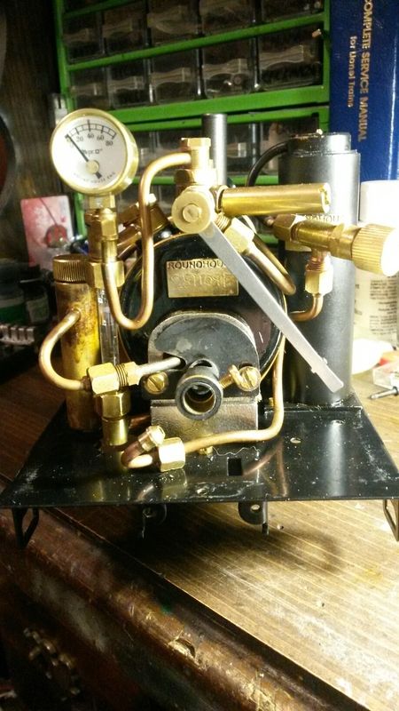
That plug is where the water site glass mounts. Here is a pic of my Sammie’s fully outfitted back head. Mike

Ok, then the pressure gauge on yours looks like it’s connected to a copper tube run from the fittings at the top of the boiler.

In the top photo, what is the pipe pointing to the 4:00 position, right next to the throttle, it looks like they both attach to the same fitting as the copper tube going to the pressure gauge?

The pipe near the 4 o clock position is the gas feed line to the burner jet(which is removed in that picture), the line is passing just out of sight, but it leads to the gas tank control valve. No boiler taps at the 4 O clock position. Only at the top, the the pair on the other side 8 and 11 on the clock for the sight glass. Mike

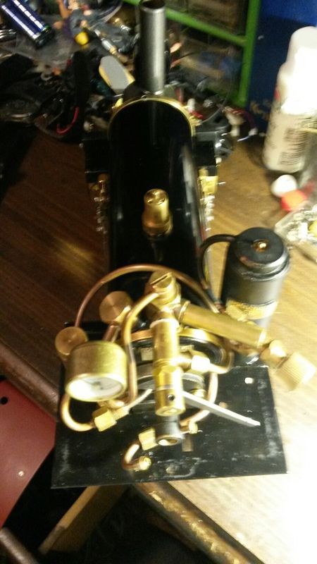
I see the gas feed, that pipe I’m seeing in the second pic, has a slot cut into it

Mike Wlez said:

I see the gas feed, that pipe I’m seeing in the second pic, has a slot cut into it

It is the filler for boiler water, hose from pump bottle goes in slotted end.

What he said! Thats the goodal valve as supplied from Roundhouse. Mike

Ah, ok,… I guess if I had bought that part, instead of deleting it from the original order, I’d know, Thanks gentlmen.

Well, that was short lived…, engine is fine, but the nice blue paint I put on the cylinder covers burned off. I’m thinking I should have used self-etching primer instead of a standard rust-o-leum primer. Any suggestions as to which brand is better?