Like many I purchased a few of the trackside Details new marker lights when they were introduced several years ago. After looking at one pair and fiddling with the brackets that came with them, they went back in a parts draw to be hauled out on occasion but quickly reminded of the mounting issues, back in the drawer. One of my projects nearing completion is my version of the business car Rico, for which I wanted to mount a pair of these lamps. I 3d printed the cars ends so I could include a mounting feature to support them. Another issue is that the base of the lamps mounting flange is not adjustable, and is only meant to mount on the cars sides. Many lamp brackets were mounted on the curved portion transition from the sides to the ends at 45 degrees. Final condition is that I want zero wires showing on the outside of the car, but still have the ability to light the markers. I have long pondered this capability, along with having the ability to plug in these lamps, so I could swap from end to end of the car. I have given up on this part for the moment, and concentrated on just losing the wires from an incandescent or LED Lamp.
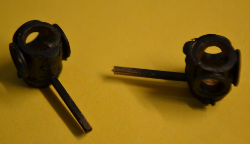
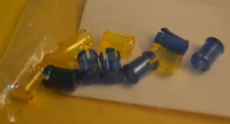
the brackets from Trackside details that are available (top) and supplied with the markers below:

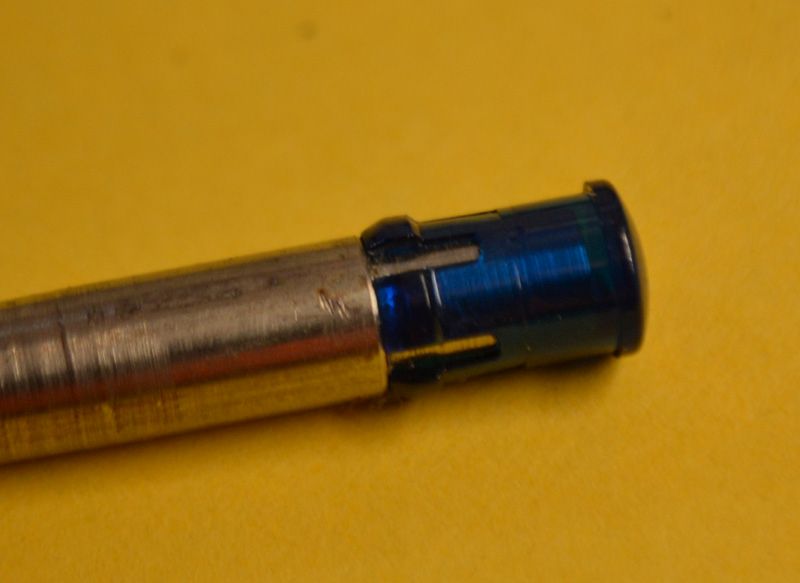
To start off I cut off the existing bracket back to the base of the lamp, and file it smooth. If you are going to make lamps that mount on coaches then you need to make a mark/dimple with center punch at 45 degrees from the existing bracket position, centered vertically on the width of the bracket band. Otherwise make your dimple on top of the old bracket location. If you are making a 45 degree set remember to make them up as opposite hands. Next I drilled thru to the inside cavity with a 1/32 drill to verify that I cleared the cast in bottom of the marker. Subsequently I drilled 1/16 them the final drill is .081 dia. this is the across corners dimension of the tubing. These may not make it all the way into the central cavity, and really you only want to just drill thru the outer wall. Next you need to find a piece of K&S 1/16 square tubing. I suspect it may be hard to find but I had plenty for this project. I cut them about ¾ inch long. Very important next step is to silver solder this square tube into the round hole. Be sure to keep it square in all directions while it cools. The next step is to melt some soft solder opposite the new mount near the top of the lamp. I will use this to solder the negative lead from my LED to. Now I verified the center of the tube is clear by threading some small wire thru the tubing into the center of the lamp. Prepare the lamp tops by making a notch in the mounting pin. This is to clear our lead/solder connection. Please note that the correct orientation is the tips of the cap are aligned with the lenses. I formed up some .015 brass wire for the handles. I next took these and cleaned them of any soldering residue and painted them flat black. Sorry there are no pictures of the above steps.
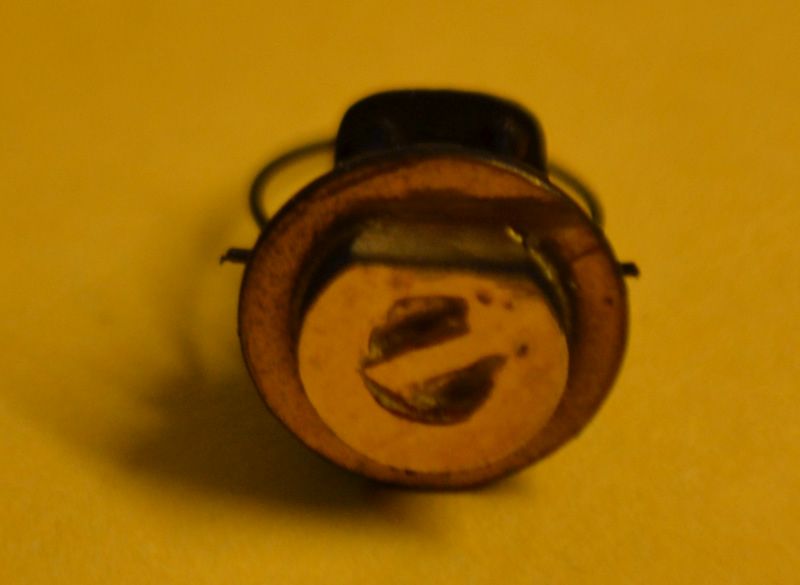
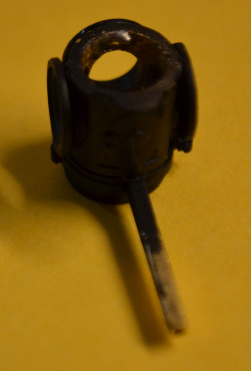
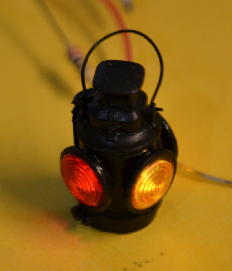
After the paint dried for several days I started assembly. First thing is to thread in the positive wire, I believe the wire I am using is Mini tronics 30 gauge ultra-flexible wire. It is available in several colors. Next I prepare the 3mm yellow Glow led by bending the positive lead almost 90 degrees to the top, then cutting off leaving 1/8 length. With a clean and hot solder iron tin this lead and the positive wire you fished in thru the square tubing, then apply a short section of shrink tubing. then finish the bend. you only get one shot at this because bending back will break the lead.
Next I pull the wire back thru the square tubing and position the LED in the lamp so the bulb part is centered in the round opening. This leaves the bottom just off the inner bottom. Once happy with the positon I solder the negative lead to the soldered puddle placed earlier. With a hot iron it is a quick in and out job. If I had not place the puddle earlier I would had to heat the whole casting up again. Before cutting of the excess lead, test the installation to make sure that it is not shorted out. . I have made up a quick battery setup with the resistor of choice soldered in so I can just touch the leads to test. If all is good ( I have made up six so far and all have passed on the first try ) trim off the excess lead and file the excess flush with the top of the body. Now test fit and adjust the cap portion and glue in place with ACC .
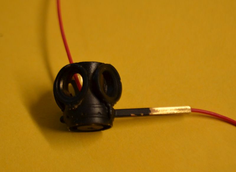
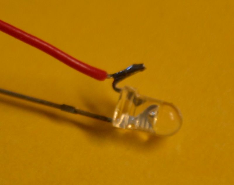
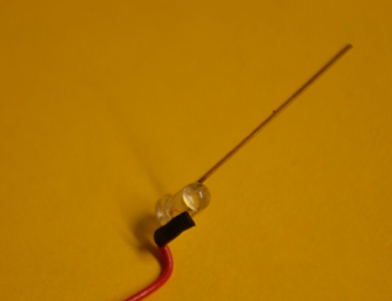
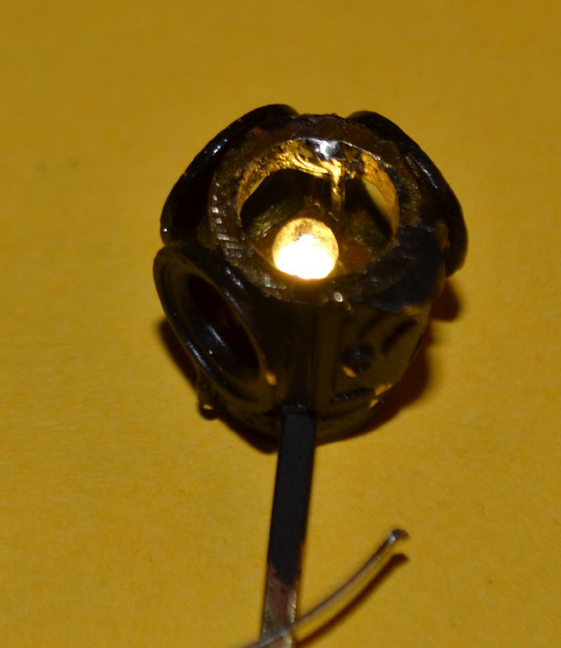
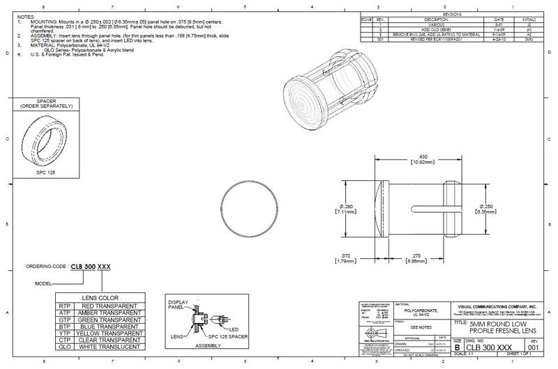
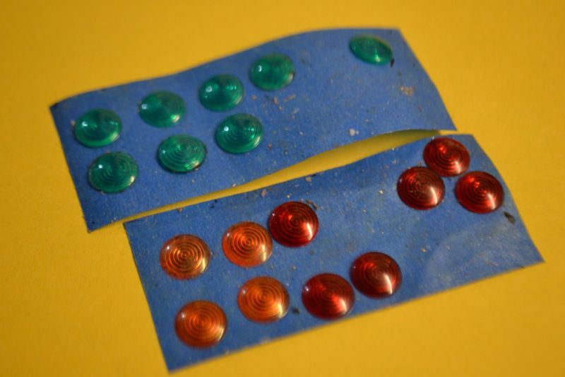
For lenses I use Mosher P/N 593-3000g and its variants, lots of these in stock. These happen to be green. Jack Thomson originally put me on to these many years ago and I originally used the on some Ozark Miniatures Markers. To start this process I made a mandrel out of ¼ round stock, and turned down a portion to fit snugly in the lenses, but short of the internal bottom. This is so the area is relieved for parting off the lens part I need. I part these off using my Taig Lathe, but you can do it with practice on a power tool. When Jack originally did it he just cut off the end so that is an option as well. Glue the lenses in the appropriate place per your railroads practice. Test the function again.
Now on the car side I drill a 1/16 dia. hole in the desired location, and using a small square file I square up the corners. In the case of the Rico observation end I put the square hole in the 3D printed part. If you are concerned about the small size of the square hole you can go up one size to 3/32 and use a section of 3/32 square tubing which the 1/16 fits right into. I had considered this as part of my plug in plan, but had not solved the positive connection. One last piece of this puzzle can from Model railroad hobbyist magazine in there January issue. It discussed something I didn’t know existed.
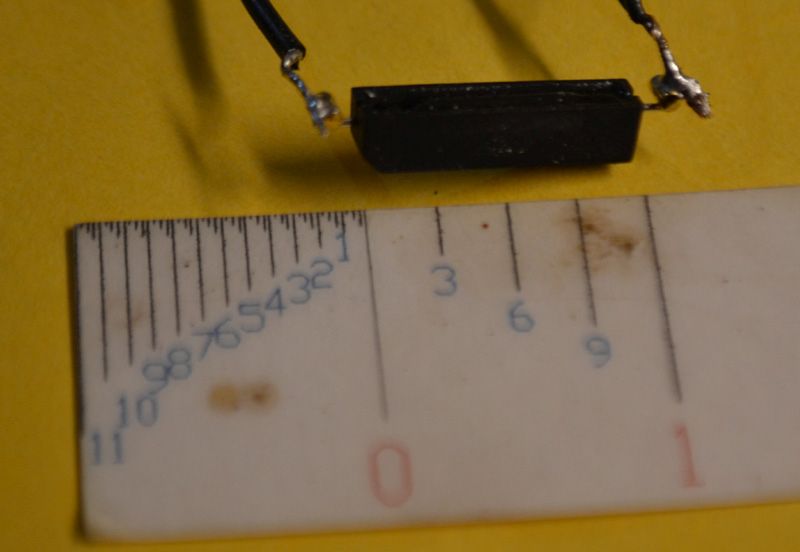

Latching Read Switches, wow! Availability of these is limited, and I settled on the one I did in part because of its form factor. Many are in glass tubes, and I have seen discussions that these can be brittle. This one (info below) appears to be in a plastic case with the switch potted in. and the great thing is that the range is phenomenal so they can be mounted internal to the car. All the cabooses will be mounted near the smoke jack, so a quick wave with a magnet within about 1-1/2-2 inches will activate.
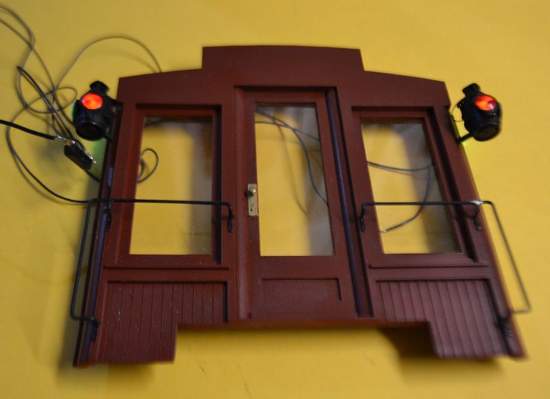
This is all the wiring I need in the Caboose, using a magnet near the smoke jack turns the lights on and off, so as long a crews turn these off at the end of there runs this should last forever. probably could use two AA or AAA batteries in a battery clip as well.
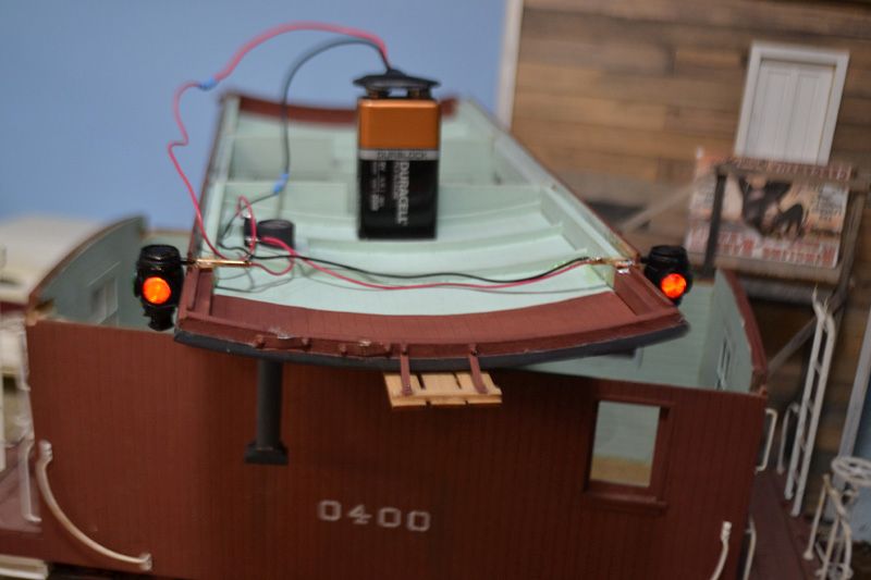
The last thing I will say is please ask questions if I missed something. I have one question as well. these photo’s were taken at high resolution , then cropped and resized in photo shop. at this point they are very fuzzy in the display, but not so in the high res originals. I have been using macro mode on my camera as well. so is the a better way to get sharper pictures to display?
Al P.