Large Scale Central

Howe Truss design?

Fred Mills, BSc, BS, SD (Hons) said:

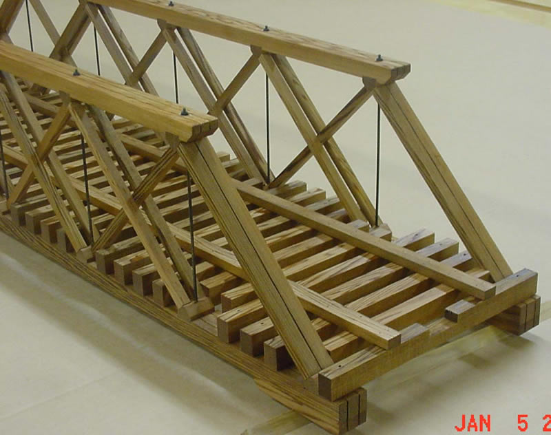
I sit back in wonder, and keep wondering WHY…is so much effort put into these lovely models of railroad bridges, no-mater what names are put on them; but few modelers, when building the bridges, take the trouble to properly build the deck. The decks stand out like a sore thumb, when so much effort has gone into building the bridge, then just regular track is layed through it, even in most cases, without guard rails. True, some bridges didn’t have guard rails, but most did. The ties on the bridges were much longer than regular ties, and the structure under the ties, is an intricate part of the whole bridge.

When designing the bridge you plan on building…please take the same effort you put into the structure, and apply it to the deck of the bridge. When you do; you will see a much better model, that you can truly be proud of. Rail and spikes are readily available…use the plain steel spikes, and wet them so that they will rust, and then not pull out of the ties.

Please take this note as CONSTRUCTIVE criticism…with the hope that some will appreciate the well meant thoughts.

Fred Mills

OK Fred,

So now that I understand how the trusses should be made, how does one make the decking to be correct. I don’t have any problem hand laying the bridge rails so they are right. So how does one make it so it is correct with walkways on both sides?

This looks like it has all the right elements.

even though it is a pony truss and not a through Howe truss it has the wedge blocks and the tie rods going through the blocks and stingers. I also envision the ties being right on this one. Is this what one would call a proper deck?

Basic elements of a bridge deck are: very wide , larger ties, (can be full width under walkways, if walkways are on top, some hang over side) spaced closer together. Inner guard rails that DON’T keep the wheels on the rail, they DO keep the wheels on the ties and help to prevent rolling stock from pitching over the sides.

Outer guard timbers at the edge of the deck.

John

PS; your bridge is very simplified for G scale (http://www.largescalecentral.com/externals/tinymce/plugins/emoticons/img/smiley-embarassed.gif)

Whilst out in Bollmanville I ran across this site that should be an over all help, including bridge plans with a look at details…

http://freemodelrailroadplans.com/

John

John Caughey said:

PS; your bridge is very simplified for G scale (http://www.largescalecentral.com/externals/tinymce/plugins/emoticons/img/smiley-embarassed.gif)

That isn’t my design it simply shows some of the elements. I am leaning toward throwing this:

on a copy machine and blowing it up to the right height and then cutting it to length to make a 60’ span (36"). This way I can’t go wrong since Howe himself drew it. Not to mention I like the design.

Thanks for explaining the decking. Is the inner guard rail (I assume you mean between the rails) the extra rail looking things? Then heavy timbers for outer guard rails out by the trusses with the walkway planks in between the outer guard rails and the rails. Or would it be inner guard rails-rails-heavy timber outer guard rails- then planking? The latter would make sense to me.

Also for 1:20.3 how wide should this bridge be for clearance, as well as height. I am thinking making it so it has 10" clearance above the rail head. Is that about right?

Only inner guard rails, often they are brought to a point several yards if curved off the bridge, shorter if straight. Often older lighter worn rail was used. As main lines were up graded old rail was recycled as sidings, if the rail heads were ok and in lesser jobs as wear dictates. Equipment grew as it improved, heavier rail was needed to support them.

Wood timbers on the out side edge. No wood guards between rails and outside edges.

The wooden timbers on your picture bridge are to hold section/flex track. We want you to hand lay, hand spike your rails to your ties… so ignore those.

I’ll defer to those who know 1:20.3

John

I am thinking something like this would be accurate only with an inner guard rail made out of old rail. So it would have and inner guard rail bent to points, hand laid track rails, then a heavy timber outer guard rail, then the planking out to the edge.

Is this what your thinking John?

I blew up the truss picture so that the overall height of the bridge is 11" and in doing so the two ends up to the first truss rod would be 11" each and the center sections between truss rods is 7.5 inches. So if I do the two ends and two center sections that would make the bridge 37" long. Now what about width for a single track and a walkway on each side like above?

How about bamboo

Did the prototype have guard rails Devon?

Don’t know. Since I have no picture other than one where the bridge is underwater and I have no blue print or drawing I have no clue. The track profile does not say one way or the other. So your guess is as good as mine. I am certainly certainly open to theory on whether a small cheaply made narrow gauge would have them.

I do like the looks of the guard rails especially old rail ones on the inside coming to a point. Now whether or not they were present don’t know. Same with planked walk ways. Again a looks thing to me.

This covers it…

This might be more your speed… time and location are close…

It’s pin connected construction.

Inside a bridge structure you don’t need the out board timbers…

John

Thanks John,

That picture does show the decking well. I love the steel bridge but It just has to be wood for personal preference. Steel just doesn’t seem “right” to me even though I know it very well could be.

Not needing outside timbers on through bridge makes sense. I think I have a good idea now Of what a bridge should be. Now I just need to make it. Thankfully I have all the cedar one will need to build it and the wife is out of town this weekend. So we will see what happens.

Devon

John wanted you to build the wood one in the background!

I would love to see a detailed shot of the one in the background. Now thats an eye catcher.

Ha oops I must be near sided didn’t even see the bridge in the background. That one in the background is cool.

Don’t forget to allow for the escape platforms. They usually held a water barrel, as well, for fire fighting purposes. There are two in the photo of the deck bridge, above, that shows the guard rails.

Devon Sinsley said:

Thanks John,

That picture does show the decking well. I love the steel bridge but It just has to be wood for personal preference. Steel just doesn’t seem “right” to me even though I know it very well could be.

Not needing outside timbers on through bridge makes sense. I think I have a good idea now Of what a bridge should be. Now I just need to make it. Thankfully I have all the cedar one will need to build it and the wife is out of town this weekend. So we will see what happens.

I believe that’s an Iron bridge… paint it brown!

Eric Schade said:

My covered bridges use How trusses. this test of the strength of the bridge is before adding the truss rods, which also add strength.

here is the bare truss so you can see what it looks like. the thin stringers running the length of the bridge will hold the siding.

the cedar roof and siding keep the weather out and protect the bridge truss. these bridges are made from #2 pine and are left out all the time. my oldest bridge lasted 20 years in the weather. it was replaced because it was too small. It was perfectly weathered…even had a few replaced siding boards which were also well weathered!

Eric I do not think after doing that much work I would have the testicular fortitude to attempt that test, besides the fact I am probably 50-60lbs heavier than you, I would cry if as soon as I stood there it went CRACK BOOM, kindling. Cannot wait to attempt to build one myself, getting materials assembled now. Great job!

KALMBACH Bridges and Trestles for good info…