Large Scale Central

Help with Shapeways Model

This is for those of you guys that have successfully created and printed stuff at Shapeways.

What’s the best way to upload models? I’ve got 4 separate parts designed, and scaled down correctly. When I upload them to Shapeways, using the Ultra Frosted Detail, the total cost is $10.01 for one print. I need 4 of these, so I’m looking at $40.04, (I’m open to casting this, but I’m not sure the size is big enough for a decent cast). Not bad, but I’m wondering if the way I am positioning the parts would either increase or decrease the cost of the print? The biggest of the part is ~1" x 2", but Shapeways shows the total print area as the following

Size
Cm:8.24 x / 1.562 y / 3.908 z In:3.244 x / 0.615 y / 1.539 z

Part Count 4
Material Volume 1.4345cm3
Machine Space 3.3248cm3

Surface Area 18.9723cm

The other problem that I’m having is one of the parts isn’t uploading right as it converts from a .skp to .dae file. I noticed this on the preview the Shapeway model.

Thoughts?
You only provide a position if you want it printed a particular way, otherwise they will position it to work the best in their system. There will be a cost added it you have 4 pieces in one print, which is what your part count indicates. As far as your size difference, they are taking into consideration overall space it will take to make your part, including any clearances and/or support required.

Chris

Depending on the material, there is a base charge per file. Then they add a volume charge on top of that. With FUD, its usually cheaper to put everything in one file. Other materials, like brass, they won’t allow multiple objects in one file.

I upload in .stl whenever possible (I paid for a Sketchup plugin to do it) because the files are smaller. You can export .obj files directly from Sketchup, but they are larger. STL usually works fine, but sometimes it’s quirky and leaves out part of an object.

I tried placing the 4 objects closer together and uploaded the new file. This reduced the cost to $9.37 so some more placement is in order before I hit submit.

Thanks for the tip on uploading in .stl, I will try that. I had been uploading in .dae. Still have a few more minor details to correct in the model, but overall this is going a lot faster than it would be scratchbuilding the parts. I will try to upload a picture of the parts and the drawings so everyone can see what I am discussing.

Craig, for frosted ultra, the price sounds similar to what I’ve had done, maybe better.

Your part count is 4, so it looks like you need 4 prints of four parts. Is that correct?

SW adds a per-part fee, in addition to overall “machine space” (volume it takes up) to all else. By “part,” they mean separate bodies contained in the same file. I’ve had some success in cost reduction in combining individual parts with “sprues” connecting them. So if you have the means to do so, I’d recommend making a small (say, 1/32") connector between the 4 parts to unify them, and getting that priced.

Further, you might attempt the same for the overall order, that is, array the four-unit set into a four-layer stack, or otherwise nest the 16 parts into the smallest overall volume possible. Then put more “sprues” in to connect the layers, and otherwise ensure each part is joined in one or two places. Your part count and file count would be 1 for the entire job, with minimal “machine space” taken up.

Best luck,

Cliff

Thanks for the help and suggestions. I’m still tweaking the model to get everything correct.

Another question came up as I’m designing these parts. Since they are hinge pieces, can I design and therefore, print them as working hinges?

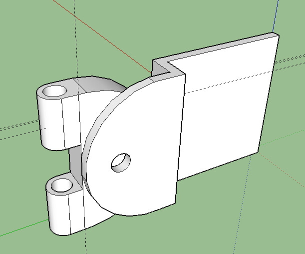
Does anyone know or have experience with this? I know that when drawing the lines, technically a ‘single’ line has no depth. It’s merely a reference point until some sort of depth is added. In other words, can I back both parts of the hinge ‘back to back’ with 0 clearance, not connecting the two pieces, or do I physically need to design in a minimum clearance of say 1mm (or whatever the minimum for FUD is?). I hope this makes sense.

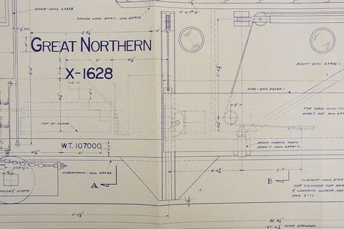
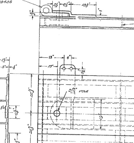
Here’s the drawing. There are two parts that move. The far left is part of a larger horizontal hinge, and the smaller hole to the right will be a vertical hinge with a pin. As they are drawn now, they are two separate pieces that are simply overlapping.

Hinge Drawing

I’m not entirely clear on what your question is, but the photo you posted looks like it would print as one object. Maybe you could show us some different views?

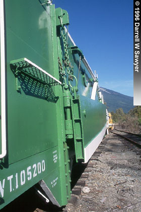
I guess I didn’t explain my question very well. Can you print the hinge as a working hinge? I did a little searching and yes you can design working hinges, but they don’t seem to work that great in the printing stage. I will instead just print them as separate parts and connect them with a brass rod like I was planning in the first place. After looking at the photos of the prototype and my drawing, I need to redesign.

They say you can print interlocked parts in certain materials, but I have not tried it. Instead of an interlocking design, I have always opted for two separate parts that I can fine tune with a sanding stick/file.

This is the part drawing I’m working on.

DSCF0564

Hinge Drawing1

bn972514-17

Okay, I need some more help with Shapeways.

I’ve uploaded the finished model to Shapeways in various formats and each time, in the preview section the NBW detail isn’t showing up.

I can attach the file if needed. What I see is that the washer detail is showing to be printed, and it is designed as part of the body of the piece. The Nut/Bolt piece is a different component on the Sketchup file that is layered on top of the main body piece and the washer detail.

Edit: I also noticed that in the heat map view, part of the model shows as less than .3mm thick, even though I went back and changed these parts from .289mm thick to .3mm. The uploaded file isn’t showing this change when it converts from the .skp to the various file types.

Any ideas on how to fix this?

If the NBW detail is disappearing, make sure you don’t have a loose shell. Sometimes it looks like two components are butted together in Sketchup, but Shapeways thinks they are not connected in the export file. A simple hack is to make the NBW about 1mm deeper than the surface it resides on.

I have also experienced what you’re describing with updates not being reflected in your new file. Try manually deleting the export file before you save a new one. Or, export it to a different directory. (This seems like it may be a caching issue in the web browser.)

What material are you using to shoot for a .3mm minimum? Sketchup sometimes has trouble with dimensions that small.

Thanks for the hints. I’m trying to print in FUD, and shapeways shows for that a minimum of .3mm for a supported wall and .6mm for unsupported.

I originally drew in 1 to 1 scale and than downsized to 1/29 because I knew that sketchup was getting funky at the smaller scales.

A habit I have picked up while learning to use Sketchup is to calculate what the minimum thickness would be in 1:1. By that, I mean: if they say 1mm, and I’m modeling 1:29, I draw my 1:1 minimum at 29mm.

I also make whatever I’m working on a component, and have one full sized instance of it in the .skp file, and a scale version. That way I can go back and forth between the two as necessary.

If you generate a lot of components, it can slow the app down. Hiding the “outliner” tool window will help it speed up most of the time

I don’t think that I have too many components in the model, bit that is a good thing to remember.

Thanks for the tip too about making things 29mm tall for down scaling. On this model I tried using the scale tool to resize instead of using the tape measure tool to resize.

These NBW details are killing me… I went back and extruded the NBW backwards into the face, and on the Shapeways preview they still don’t show as details. Arghh. Back to the drawing board again.

Also, the thin walls are showing up again despite the Sketchup model having them at .3mm thick. I will remeasure and double check again, but they are close enough that Shapeway is okaying the print as is.

I’m about ready to say screw it and place and order, and just add NBW details on my own if I can’t figure out why they show on the Sketchup model, but not on the Shapeways. I will try extruding them even more to see if that helps mesh the two parts together.

What kind of file are you uploading? If its a .obj, can you tell me what options you have selected? On the “Export Model” dialog, there is an “Options…” button at the bottom that will show you.

I tweaked the model late last night and extruded the NBW a bit more and they showed up. I need to double check everything once more but this first part should be ready to order.
I’m debating if I show upload the other parts in drawing into this same file for a higher part count total, or upload 3 different files. The total number of objects will remain the same, but I’m thinking it might reduce the handling fees and lower shipping?
Example: the drag wing has 5 pieces. But I also have another. Hinge pics that is 3 pieces. So is it cheaper to have 1 file with 8 pieces, or 2 files one with 5 and one with 3?

Burl Rice said:

What kind of file are you uploading? If its a .obj, can you tell me what options you have selected? On the “Export Model” dialog, there is an “Options…” button at the bottom that will show you.

Under options on the .obj the ones selected are; “export texture maps” and “swap ZY coordinates, Y is up”

Latest update… All but 6 washers are now showing in the shapeways view…

Edit: I downloaded the program that Dave mentioned in Devon’s thread, and when I view the .obj file all of the washers show up as drawn. So is the drawing correct and Shapeways preview isn’t showing it right? Or is something happening with the .obj file when I am uploading it to Shapeways? Stumped…

http://largescalecentral.com/forums/topic/26639/3d-printing-and-sketchup/view/post_id/333558