Large Scale Central

Full Control R/C in Bachmann C-19

I will be gutting the electronics in mine over the winter, replacing the Revolution/Phoenix combination currently in it with a TCS WowSteam decoder. I’ll also be adding a speaker to the boiler, as the TCS gives me two speaker outputs. I plan on re-purposing all of the wires running between loco and tender, but the rest will become history.

Later,

K

I’m not going to go that far so my changes will be reversible with some soldering. I’ll keep all the electronics in the loco itself. I plan to be able to switch the class lights and the cab lights on and off from my remote just for fun. As such I will still need to supply the B+ voltage to the loco. That will be part of the bread boarding to figure out if I can do that easily.

I’ll be interested to see what speaker you are able to tuck in the boiler and where. That is my biggest complaint on steam locos with sound as all the sound follows the loco rather than leading it.

Alec Escolme said:

Sounds interesting Jon, after installing a Deltang R/C and Phoenix sound system in my K-27, while retaining the stock boards, I found it was more work than two wires to motor and two wires to the headlight.

I have got two more socket equipt Bachmanns to convert with limited bunker space (Climax & Forney), might have to rewire…

Where is your battery pack located?

I have a flat 4-cell Li-Ion pack that was sitting on top of the circuit board. Where I will be able to locate that now is yet another question. If need be I will bust it open and put two on either side of the new speaker enclosure.

Al Pomeroy said:

Jon,

I never documented it but I do remember adding a 5volt power source to power leds and chuff sensors after I removed most electronics. I only have one of the two connectors between tender and loco in place. went from 14-15 wires to seven. did not power the smoke generator but did remove it.

Yes, that will be required as the 5V step down appears to be on the tender board. You can get this an Amazon Prime for $11.20 - should be enough current and it’s tiny.

Pololu 5V, 600mA Step-Down Voltage Regulator D24V6F5

Here are a few quick pictures of the sound bar salvaged speaker enclosure. Looks like I can make it fit with very little effort…

Still enclosed in it’s factory cabinet this thing sounds great…

That is one badass washer and dryer Jon!

What’s a C-19?

" Rooster " said:

That is one badass washer and dryer Jon!

What’s a C-19?

Thank you. The dryer puts out 1.2 Jigawatts. C-19 was a very early predecessor of C-3PO

Kevin Strong said:

The headlight is controlled from the electronics in the locomotive itself. Unlike the K-27 where the headlight has a direct connection in the tender, the C-19 does not. On mine, it takes its power from the V+ and V-. There’s no way (that I could find) to independently control the headlight from the board in the tender without a re-wire.

Later,

K

Kevin - Either you do not have the electron sniffing skills I do, or you didn’t have the schematic Stan posted in this thread, I determined that connection #4 from the plug on the Engineers side (yellow wire) is a direct connection to the cathode of the front LED. Grounding this pin, through an appropriate (1K per schematic) resistor will illuminate the front LED. The anode is connected directly to VDD per the schematic. All of the rest of the light functions simply need a ground to switch on when the boiler switch is in DCC position.

You are correct that the LED driver circuitry is on the tender board. What you loose by eliminating that and going with an old school circuit is the annoying dim in reverse function (https://www.largescalecentral.com/externals/tinymce/plugins/emoticons/img/smiley-wink.gif)

NOTE: I also discovered that the VDD supply circuitry is also on the tender board, so if you eliminate that yo will need to supply 5-6 volts on the 6V Battery wire (Wire #F [Blue on Fireman’s side]). CORRECTION - Supply 5-6V on the VDD Input - orange wire on Engineer’'s side. The Blue wire on the fireman’s side as on the cathode side of a diode so voltage placed here will not reach the VDD line.

I logged and tested the function of all 16 tender wires. I will started a new thread in the Tips forum with that and the relevant Bachmann drawings.

As of this evening everything has been breadboard tested and is functioning properly. I stumbled for a bit on why the LED and the Chuff circuit was not working. I didn’t realize that the voltage conversion circuit was on the tender board I had removed. The solution that others have discovered before me, is to supply +5V using using a regulator circuit. DC to DC bucks are tiny and dirt cheap, so soldering up my own circuit made no sense.

While I wait for Amazon to deliver the DC-DC buck to supply the 5V, I hooked up a battery holder with 4 AA batteries for 6V. That solved a few mysteries and also was the source of some pretty neat explosions (https://www.largescalecentral.com/externals/tinymce/plugins/emoticons/img/smiley-surprised.gif)After getting the LED’s to work using the 6V battery as a VDD source I disconnected it while we ate dinner. When I came back to the shop I mistakenly connected the 6V battery in parallel with the 14.8V battery, within less than a minute the Alkaline batteries began exploding, one at a time. I couldn’t see them but could hear pops and sizzles as the hot paste was released. With several hundred dollars worth of electronics wired up I was just a bit nervous as I unplugged the 14.8V battery from the breadboard. I was happy to discover that it was the alkaline batteries, not any of my electronics. I had a mess to clean up, but was happy that my mistake only killed the 4 AA batteries.

I updated the connector pin-out document over in the reference forum thread. I need to make some good notes as to what hooks to what, then I’m ready to start the permanent wiring.

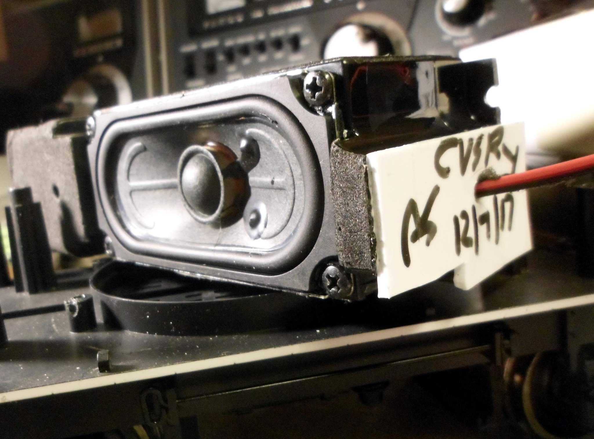
Just before midnight last evening I put the last screw in the tender shell of C.V.S.Ry. #8. What started out as a simple sound board swap turned into a major -re-wire / re-configuration job, but it is finally done. I learned and shared a lot along the way and the C-19 sounds great. The photos I took are just back from the processing lab, so I can share them with you now.

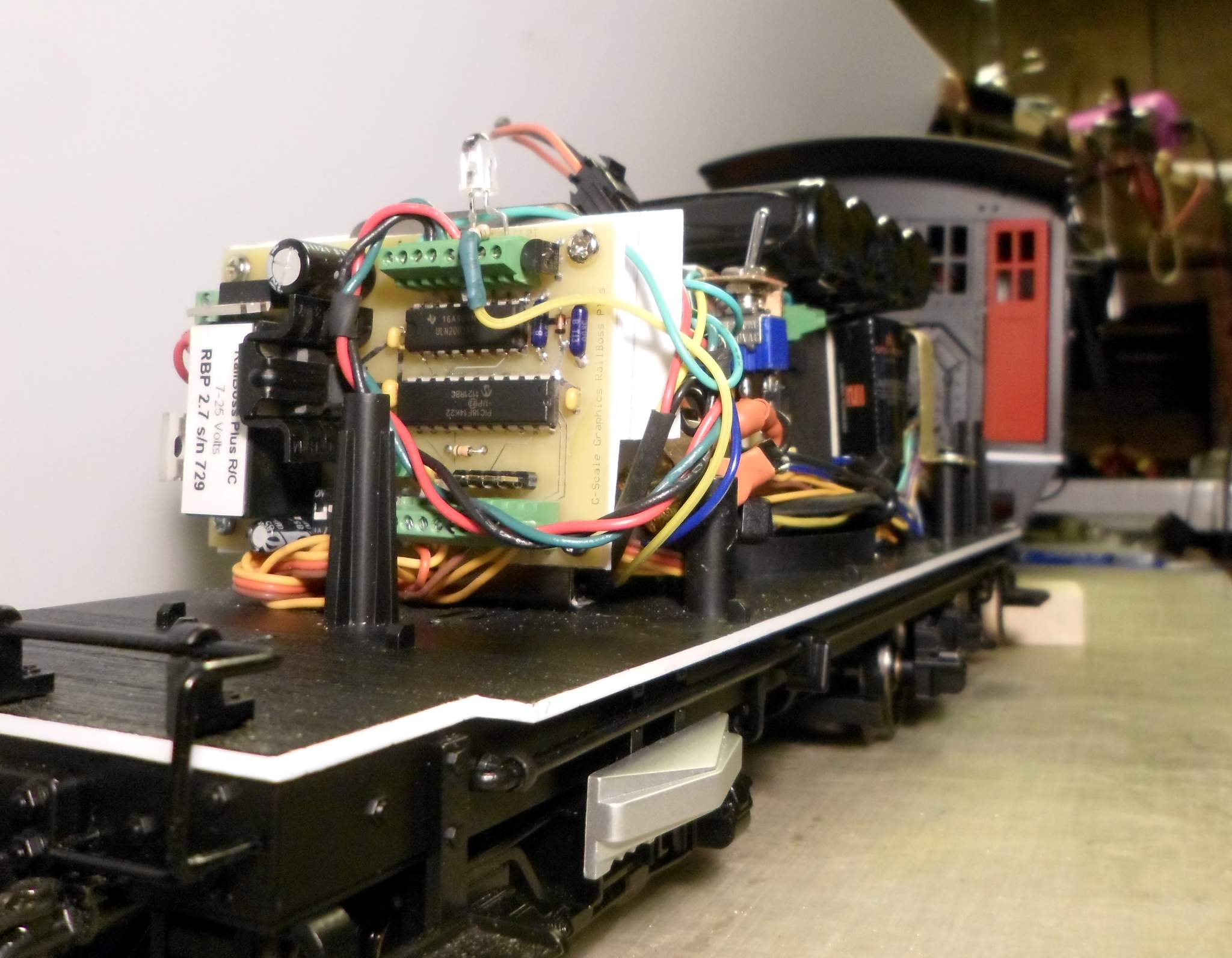
First up - View from the rear: The Railboss Plus board remains in it’s original position attached via a piece of styrene to the fan bracket (Thanks Doc!)…

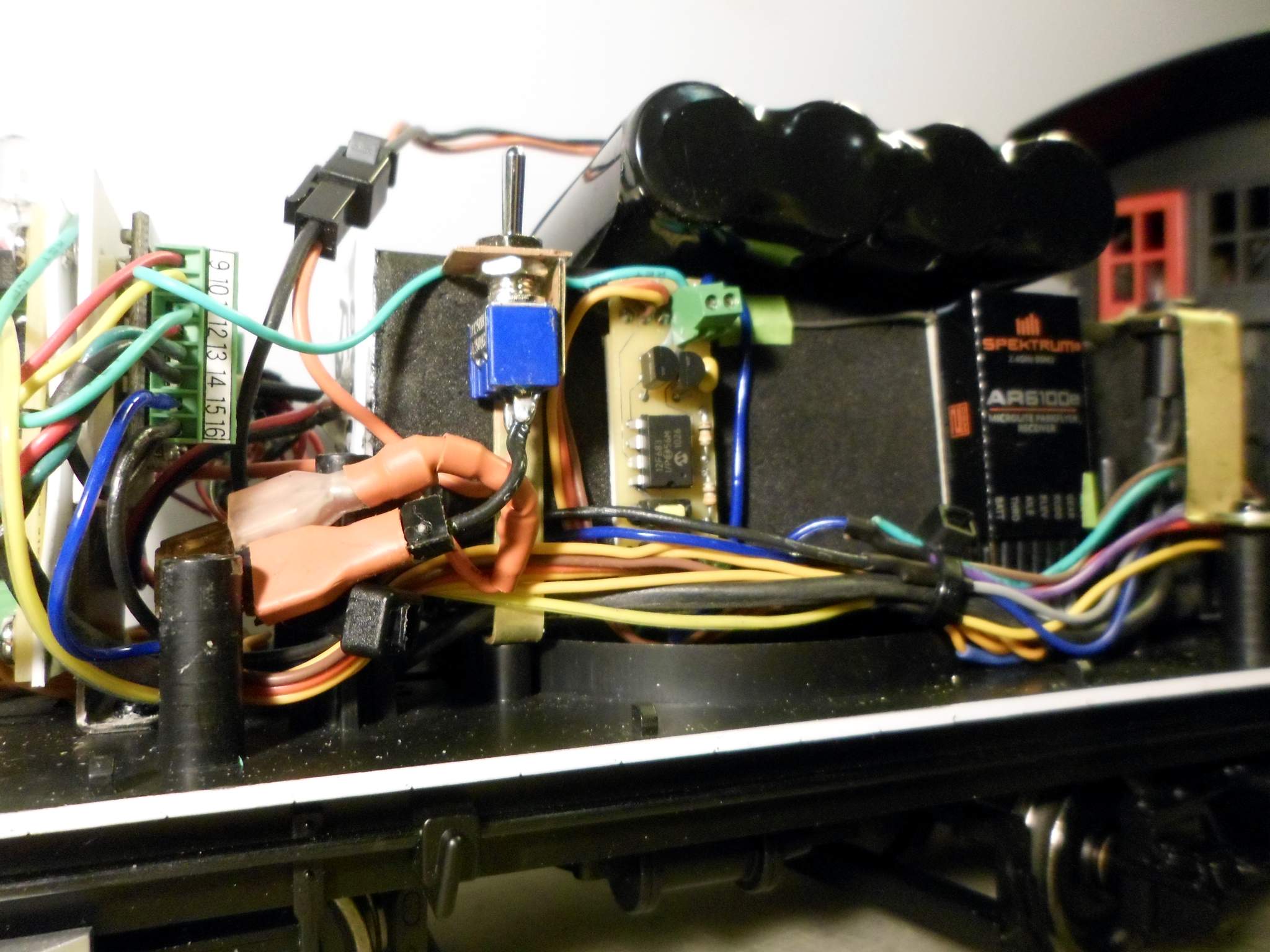
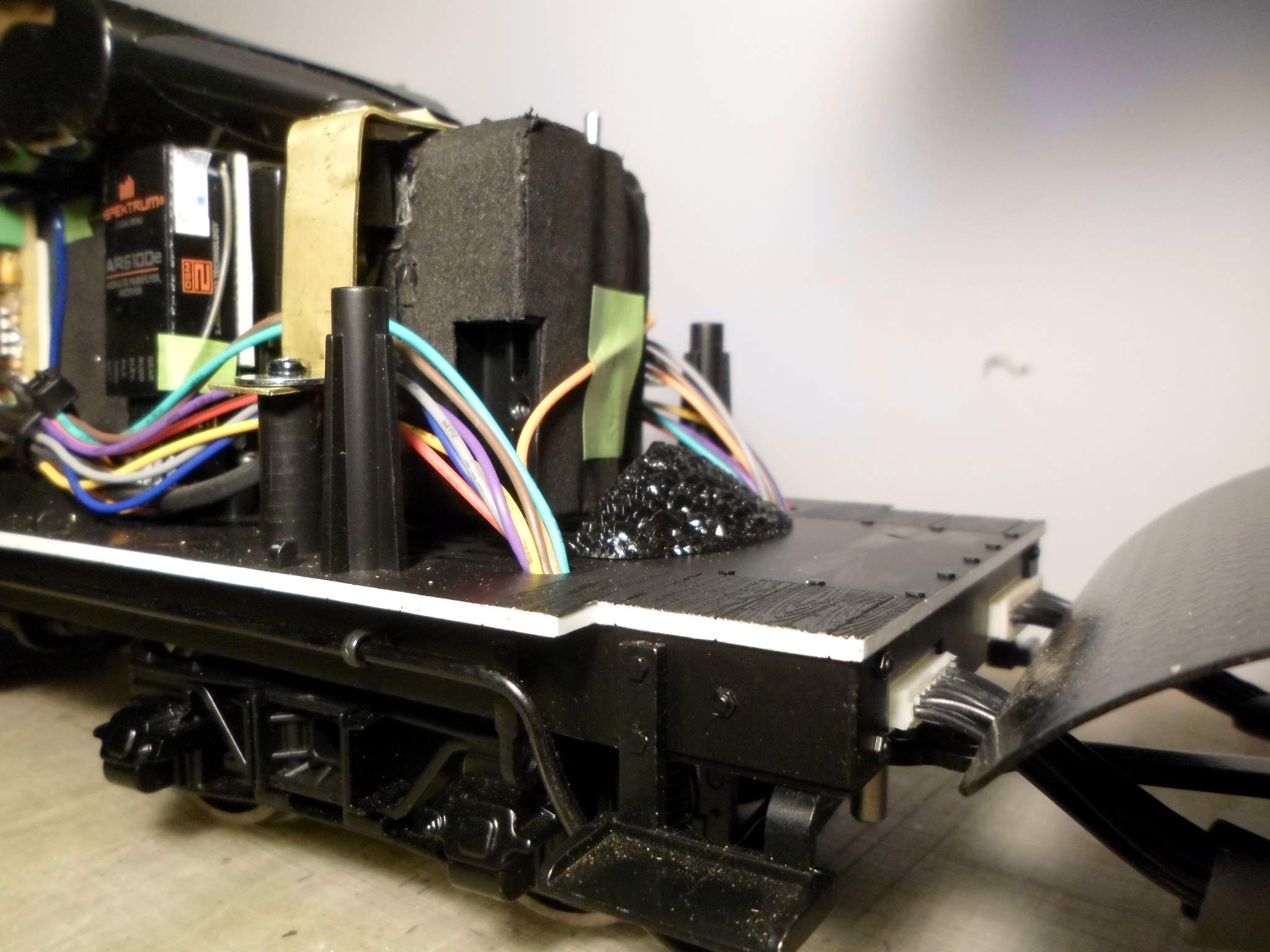
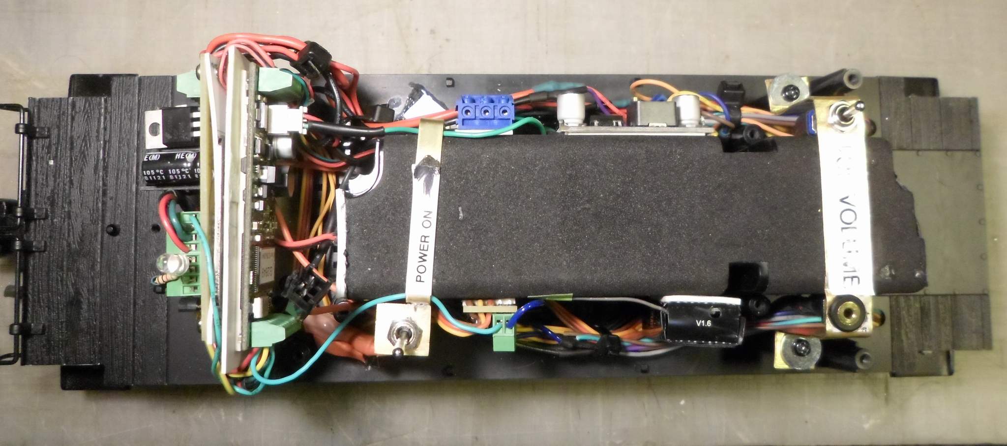
Next, from the Engineer’s side left to right: A phoenix 2K2 board stuck on the front side of the fan bracket. At the bottom a 5A fuse attached to the female side of disconnects, above that the battery connector. I soldered a switch mount to another brass strap bracket fabricated from flat stock that is used to hold down the rear of the speaker enclosure. This was the first production use of the resistance soldering set I got from Bruce (https://www.largescalecentral.com/externals/tinymce/plugins/emoticons/img/smiley-cool.gif)- To the right of the switch is a Railboss 2 Output Trigger Board. One output is a sound trigger for the Phoenix, the other turns the class lights on and off. At far right is a Spektrun 2.4Ghz receiver. A a 4 cell LiIon battery pack fits On top of the speaker …

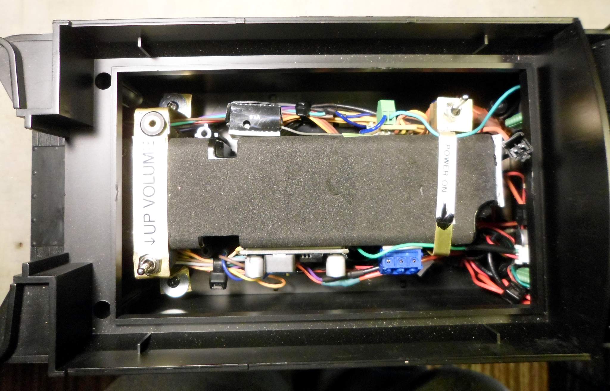
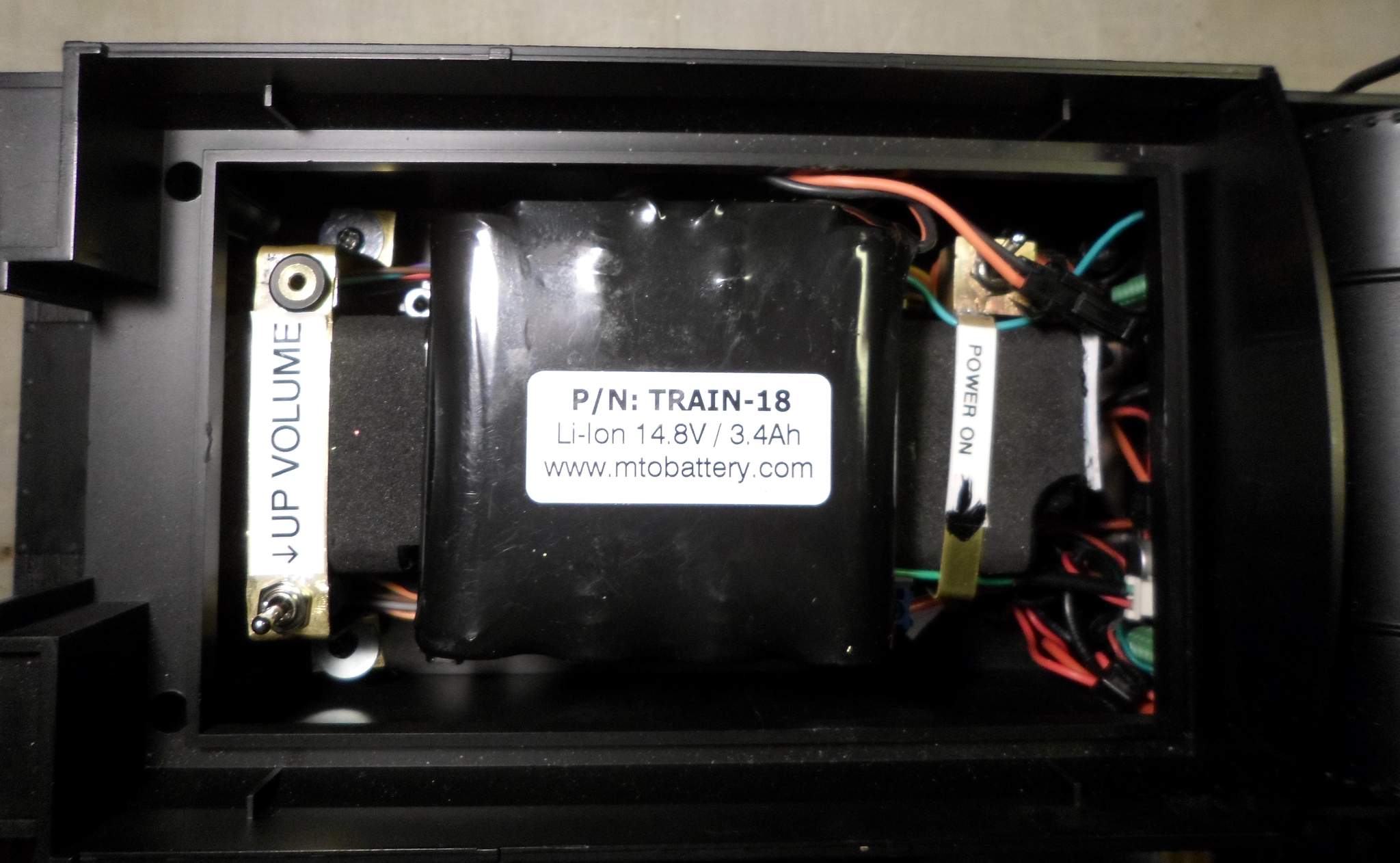
The top view - The 4 Cell Lion pack I picked up from Don Sweet at RCS New England fits nicely atop the speaker enclosure under the coal load. Doc Watson’s bracket idea at the front was re-purposed to hold down the speaker as well as carry the volume switch and programming jack for the 2K2. The new speaker hold down bracket at the rear carries the on-off switch…

On the fireman’s side from left to right: Front hold down with volume switch, a DC to DC converter that takes the 12V rear fan power and steps it down to 5V to power the chuff circuits and lights. I could have grabbed 5V from the Phoenix, but for $2 each in a 6-pack, the converter eliminates dependence on the 2K2. Below and to the right of that are terminal blocks for the battery output, and behind that mass of wires, the Phoenix 2K2 and the Railboss sandwiched on the fan bracket…

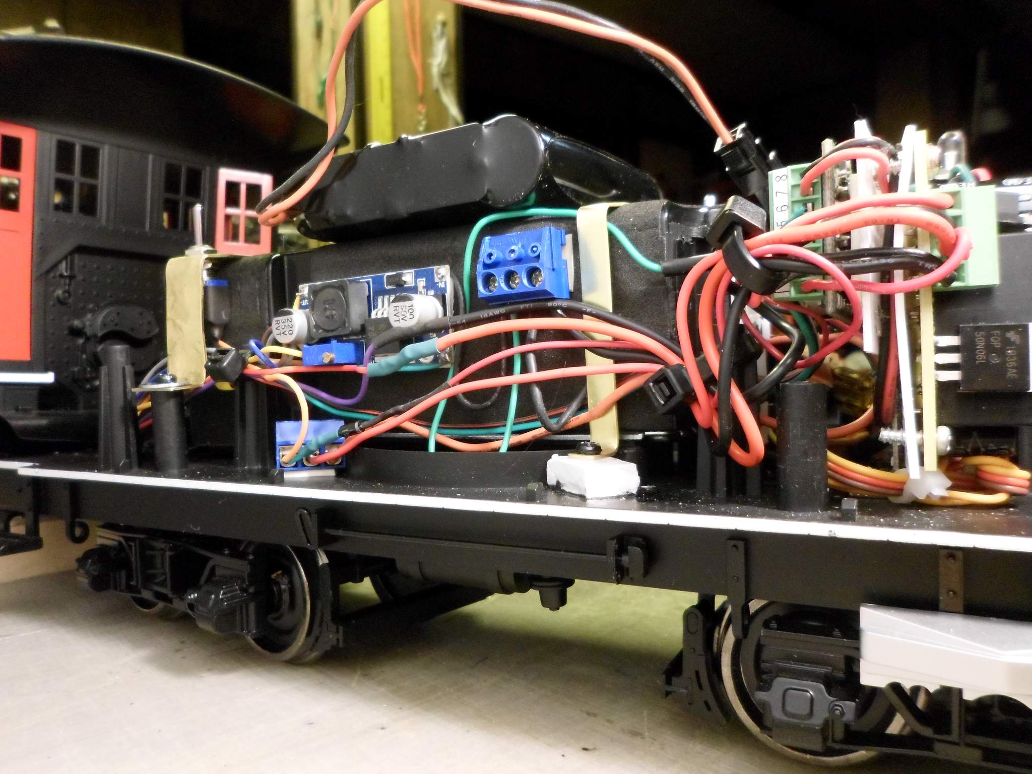
Moving back to the fireman’s side, now looking from the front, The component layout that I just happened upon worked out so that only one wire (5V to loco) needed to go to the other side. I ended up using all but 5 wires. Unused wires are insulated and still in the bundle in case I ever decide to power the smoke or do other things…

View from the top: Everything fits comfortably within the shell. No floating wires to fudge with when putting the shell on…

Another top view with the shell in place…

And finally, the battery in place - Free plug for MTO Battery. I’ve been running this pack since August and have only needed to charge it once! Guess I should run trains more…

So, the fat lady has sung and/or the fork is in the Rooster, because it’s DONE!!!

Hi John, congratulations the C-19 lives! I expect to see it at OPS 2018.

Now you can catch up on your sleep.

Merry Christmas to you and all your followers,

Don

Great install Jon. You took it a lot further then I did. Lots of good ideas.

Doc

Jon Radder said:

the C-19 sounds great.

Well, it sounds great with out the coal load in place (https://www.largescalecentral.com/externals/tinymce/plugins/emoticons/img/smiley-frown.gif)I’m getting a lot of sound pressure reflecting off the tender floor that is causing the shell to resonate badly. If I slide the coal load forward about 1/4 inch, enough pressure escapes that the resonating stops. Trying to think up creative solutions. Taking it all apart again and trying to seal the oval speaker to the round opening is not going to happen. I’m thinking I might build my own load that is acoustically porous. I don’t want to cut up the stock load - going to see if Bachmann has another available as parts.

EDIT to add: Bachmann has the load in stock. Asking Santa to order one for me.

There is always tomorrow morning to handle the “coal load”

Hi Jon, Bob,
@JRad and @rmccown-admin

Any chance you could resurrect the photos from this thread? We’re about to do some work on a C-19.

I just scrolled through the entire thread. On my posts, the only things with just a link are smileys except for one caricature of a bird with a fork in it that used to be hosted in the site freight shed. I can restore that if you need to see it :smiley:

This thread documents two versions of installs using the older RailBoss system and a Phoenix board. I have since removed that system and replaced it with RailPro. There should be a newer thread documenting that.

PM me your email address and I’ll send you the Schematic from Stan and a document I wrote up with details of the function of each wire in the two tender plugs. - Or you can just grab them from the two threads.

I’ll not repeat myself…

Pete - The newer thread is here: RailPro Install in Bachmann C-19

Interesting. Must be a Firefox thing. I see blank rectangles where the pics used to be, but if I right-click and choose ‘open image in a new tab’ I get the pictures!

I use Firefox too with no issue, but it might be the host I use. Glad you can see them with a little extra work.