Large Scale Central

For Mark Dunakin, steam loco references

Here are some links to images and animations of valve gear found via searching Google images for steam locomotive valve motion. Going to give references for both inside and outside motion. http://www.steamlocomotive.com/appliances/valvegear.php
____________-

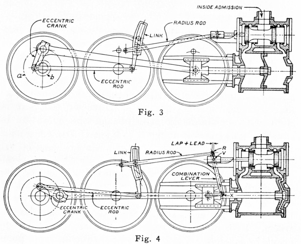
From http://www.cwrr.com/Lounge/Reference/baldwin/part01.html 21. Walschaerts valve gear is used, with an inde-pendent motion for each cylinder, but all controlled by one type B Ragonnet power reverse gear. The valve for the left-hand cylinder is operated from the left-hand main pin and crosshead in the usual way. The right-hand valve receives its lead from the right-hand cross-head, but the link for this cylinder is operated through a transverse shaft, by means of a connection to the left-hand crosshead. The return crank on the right-hand main pin is set to operate the valve for the inside cylinder, and this valve is given lead through a connection with the inside crosshead. The arrangement of the links, arms and rockers through which these connections are made, is shown in the accompanying drawings. The valve motion bearer is a single steel casting supporting practically the entire valve gear. Plan View of Valve Motion Side Elevation of Valve Motion __________–

(http://commons.wikimedia.org/wiki/File:Steam_locomotive_work.gif)

English: Steam locomotive wheels, valve & engine animation. Walschaerts valve gear (mechanism for moving the valve in a steam engine). Item 2 is a crank outside of the main crankpin. Its “timing” is a quarter turn away from the power crankpin. This provides the main force to move the valve. Item 1 is pivoted (little dot, just below the callout arrow) to the frame (light gray) in the middle, so it rocks back and forth. It has a groove (inside; not shown) along its length, which carries a sliding block, pivoted on the left end of link 3. The engineer moves pushrod 8 left and right to move link 3 up and down. If the link is below center, the engine moves backwards. If the link is near to the center, steam is conserved for ordinary running when up to speed. The short link below the numeral 3 (not the arrow) that seems to point up into the air “from the wheel edge” is pivoted on the frame (not shown) at its upper end. It supports the rest of the links below it. The right end of link 3, therefore, doesn’t move up and down much; its sidewise motion operates the valve. Item 4 is the crosshead, the sliding piece that guides the piston rod. (Callout 4 also points to a link that improves valve timing.) Note the typically-European piston rod – it’s very long, and unlike American (and some other) designs, it extends out front (to the right). The other types of locos. don’t have any piston rod to the right side of the piston. Item 5 is the pivot where the main connecting rod (long groove. shown, to make it lighter) connects to the crosshead. Item 6 is the cylinder and valve block. Pinkish color is steam from the boiler. Exhaust is white. The valve is a pair of black vertical stripes, connected together. (It’s shaped something like a spool.) As shown (without animation), steam is going into the right side of the cylinder (Item 7), pushing the piston to the left. The piston rod pushes the crosshead, which pushes the main connecting rod. (The piston is in the middle of the cylinder. Unlike pistons in internal-combustion engines, steam pistons are discs.)

http://straction.wordpress.com/how-the-steam-engine-of-the-locomotive-works/

Animating Walschaerts’ Valve Gear
by Richard Osborne
http://msts.steam4me.net/tutorials/anim_walsch.html

The heck with Mark I’m grabing the links Forrest

Forrest,

There are some great links, thanks for doing the research and posting.

Bob C.

OH, wow, thanx a zillion, Forrest!
You rule!
These are all great!

Will save all this and check it all out over the weekend.

Moocho gras!..md :slight_smile:

Dave Marconi said:
The heck with Mark I'm grabbing the links Forrest
Hehe, yeah, I didn't see this at first, till Ray just e'd me about this, as I thought it was that other link that you posted and didn't realize you made this here. so there ya go, I was lame LOL Much appreciated.

…md :wink:

Well, just so others are up to where I am at with what I started with to model things from, here is/was the ref image that I used to model with:

(http://www.md-arts.com/lw/SteamEngine_pt1_02.jpg)

As you can see, not exactly the greatest in details and you are left to pure guessing to figure things out LOL Yes, I know, large image, but I thought others might want the same ref image in case they too needed to model from something? :wink: Here’s how I am having to do all this with, in case anyone cares?

(http://www.md-arts.com/lw/SteamEngine_ScreenShot_pt1_01.jpg)

And Ray, as you can see in these images, those things on the side, that I guess you told me are actually round, mine shows them with the lower part in a split view, 50/50 over the plank and under the plank. I think you called them “air pumps”? Thanx for the other fotos you sent me too, like the blowers and such, since as you can see in my ref image there, it’s was mostly up to my own judgment call haha And you can kinda see why I thought the air pumps had that round AND flat sort of shape, since if you look at the front on view and then the side on view, it seems to make it look that way with the bracket thingy and bolts that all that is connected too? But, you all are the experts, not me, so I’ll go with what ever you guys say is correct :slight_smile: I just love old trains and want to model my own 3D train set is all hehe Can’t model the real things like everyone here, no room, no money, so this is the next best thing for me. OK, thanx again everyone. This is the best railroading forum/site that I’ve found, after years of asking other railroading sites for help on this and getting absolutely nowhere. …md :slight_smile:

She’s lookin’ Good, Mark.

Same will hold true for dome in front of cab with sand pipe behind rear driver for laying sand when backing up.

  • That round fitting and pipe under front portion of smokebox is for dumping cinders from interior spark and cinder catcher in smokebox.
    Don’t know if it was used on the go or not.

  • Drawing doesn’t show cylinder cocks on bottoms of cylinders - they were to let out condensed steam after sitting still so that un-compressible water didn’t blow your cylinder heads a hundred yards down the track or halfway back to the cab.
    http://www.flickr.com/photos/55976115@N00/3765793195/

  • That square in a circle under fwd sand dome is a washout plug for sticking a hose in that part of boiler when shopping and washing the sediment out of bottom of boiler. Somewhere in bottom of boiler would be a manhole type hatch for it to flow out of - expect it would be hidden by boiler lagging and jacketing when loco not stripped down for shopping.

  • Fitting extending up from front truck axle is for adjusting force on axle, regulating how much of loco weight is carried on it.

  • Back to the boiler jacketing - it is sheet metal over asbestos blocks which insulate boiler. Will be several longitudinal joins in each segment of jacketing with rows of screws - don’t know if you are going to that much detail. And don’t know for sure where they would be on this baby.