Large Scale Central

Dexter-Turbine Windmill Project

Devon Sinsley said:

Cliff that is just so cool. Now you made the comment that the turbine is heavy and takes time to get to speed. I wonder how the weight of your model compares to the weight of the real thing. Does it scale out heavier or lighter do you think?

No I want to see it pump water. Make a working pump and you might catch my attention. . .yeah right. simply cool my friend.

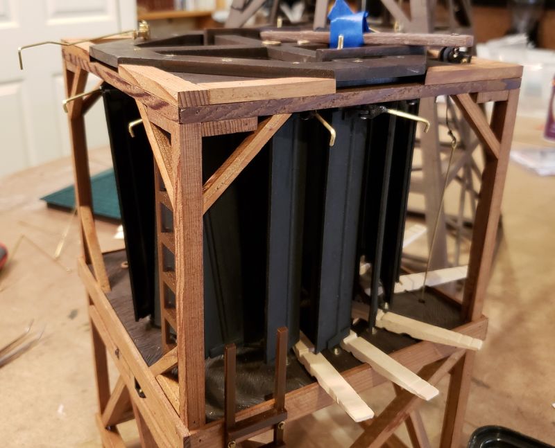
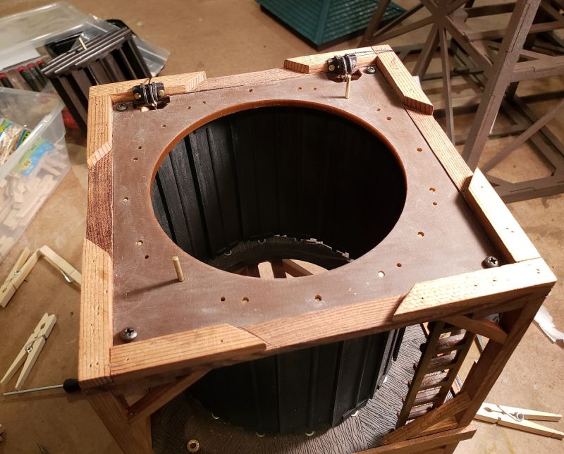
Thanks Devon, and I’m glad you like it. Dave Meashey and Jim gave great replies on the scaling of mass and force, and I sure can’t top those.

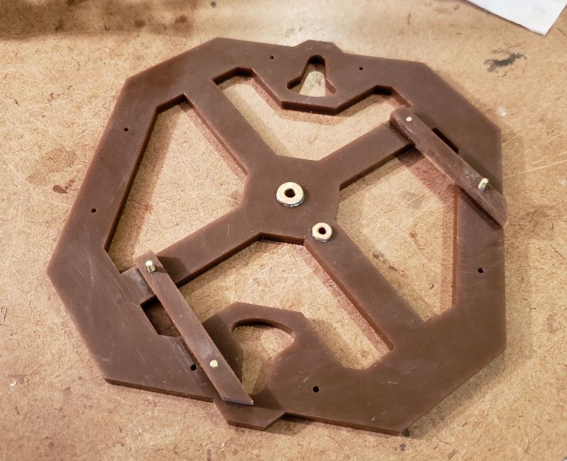
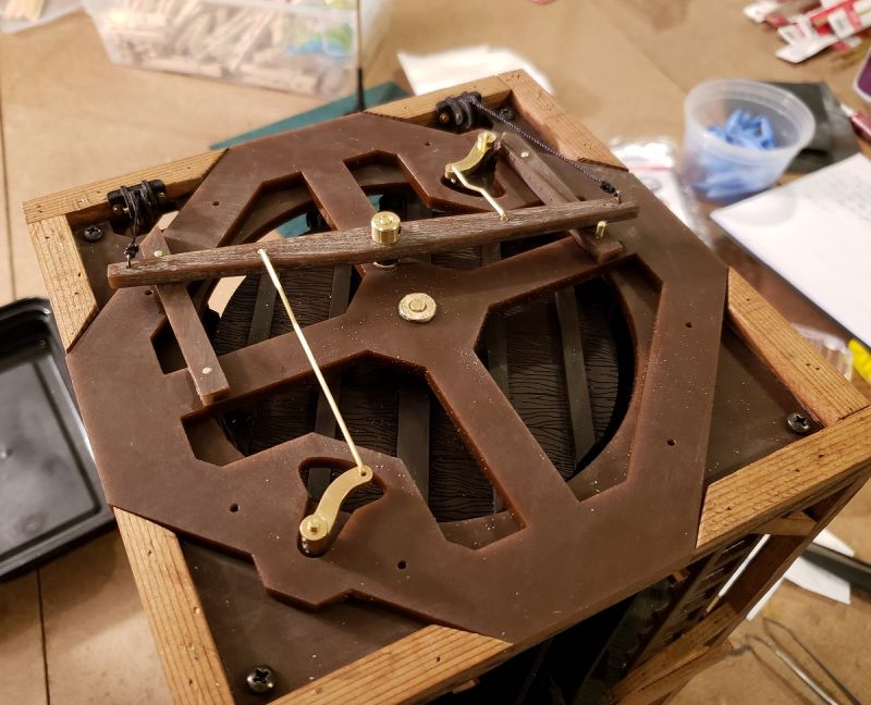
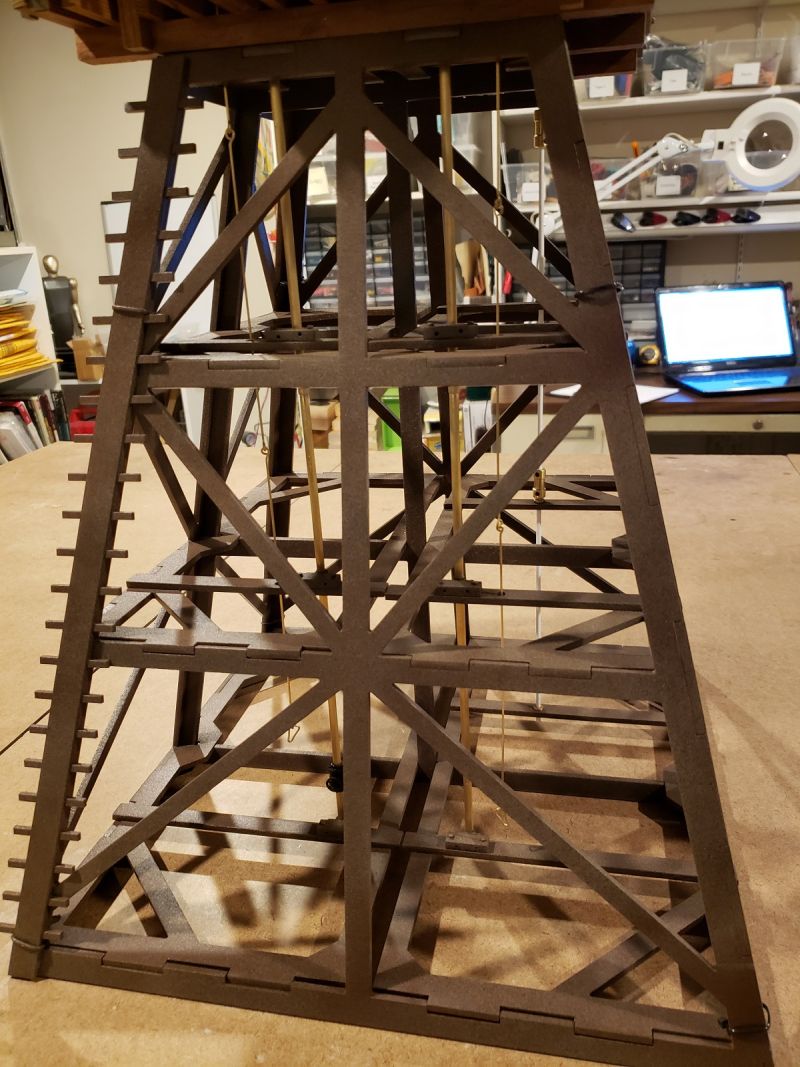
As for pumping, yeah, I get it that you and Dan would like to see that… thanks for the encouragement… We’ll see. My big objectives now are to get the vertical pump drive shaft going, and the remaining painting / weathering / clear coating done.

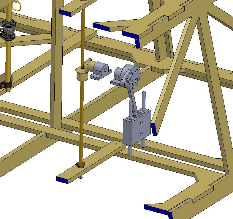
Beyond that, I’d like to do a simple mechanism convert the vertical rotation to vertical reciprocal, with a rod going down and disappearing probably. That’s because the pump would have probably been installed below the frost line, according to one source. Still working all that through.

If anyone’s seen a mechanism like that, please send me a link. The only one I’ve seen was way complicated. The most straightforward approach I think would be to do a miter gear pair, with the new horizontal shaft driving a wheel and drive arm, the opposite of a steam loco’s cylinders driving its drivers.

[edit]

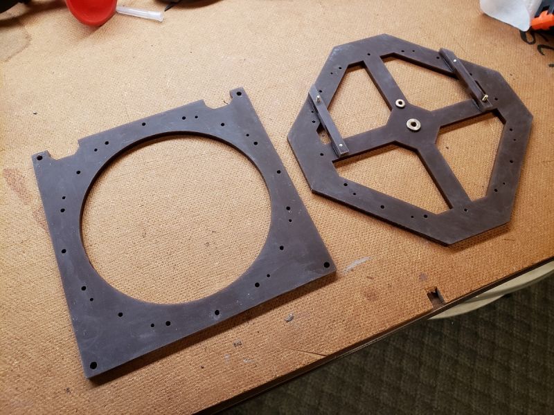
After hunting around for miter gears, and not finding an affordable pair that meets the requirements, I’m realizing that any little mechanism like this will only last a few weeks. So, I’ll probably just let the vertical shaft go into an above-ground box, and saw that’s where the pump is, and call it a day.

But, I might put a motor in the box, and let it act as a generator. Not sure, haven’t worked it out.

Thanks for all your kind comments guys, and your participation with me in this project. Means a lot.

Cliff

Cliff Jennings said:

Rick Marty said:

Cliff,

Absolutly beautiful model, congratulations on researching and building such a work of art.

Off topic a little;

In your first video at about 21 seconds in I notice a Misery Whip on the wall above the door. Wondering if you had the history on this saw, as the tooth pattern makes it look like a “Californian” produced by the California Saw Works of San Francisco. Is it a 7’ blade as it looks or is it an 8’, just curious how this saw may have ended up on the East Coast. Or maybe just an early knockoff??

Just wondering

thanks

Rick

Thanks Rick, that means a lot!

That saw measures about 66" long, and I bought it for $20 at an out-of-the-way antique store somewhere in Pennsylvania. I’m afraid I have no story about it.

So. Make one up. The more incredible, the better.

Cliff Jennings said:

Bruce Chandler said:

Wow, that is really neat to see it in action!!!

So, what is it actually doing? (Pumping Water, Grinding Feed, Sawing Wood, or Etc?). (https://www.largescalecentral.com/externals/tinymce/plugins/emoticons/img/smiley-foot-in-mouth.gif)

Well done, Cliff!

Thanks very much Bruce! I hope to show it at the ECLSTS D&B, will you be there?

This particular one, as David Maynard said, was solely for pumping water. But they were also fitted with line shafts to power various equipment.

What kind of various equipment ?

A beautiful working model. Attention to details as they say. Having lived by an old windmill as a child I have always been fascinated by any form of mill. I have a model mill on my railroad, but it is an Aldi supermarket one, but at least it is fine outdoors.

Rooster ’ said:

Cliff Jennings said:

Bruce Chandler said:

Wow, that is really neat to see it in action!!!

So, what is it actually doing? (Pumping Water, Grinding Feed, Sawing Wood, or Etc?). (https://www.largescalecentral.com/externals/tinymce/plugins/emoticons/img/smiley-foot-in-mouth.gif)

Well done, Cliff!

Thanks very much Bruce! I hope to show it at the ECLSTS D&B, will you be there?

This particular one, as David Maynard said, was solely for pumping water. But they were also fitted with line shafts to power various equipment.

What kind of various equipment ?

Thanks for asking Rooster. I’ve seen reports (newspaper articles, etc.) of them used for grinding grain, chopping straw, and running saws for a furniture manufacturer. The drawings for the huge Gladden mill indicate some possibilities. Here’s a typical Southwick ad, speaking of its various uses. Note the railroad application in the background, there the tank feeds the tender directly. I’ve only run across one brief mention of such an application, just south of Philly.

Alan Lott said:

A beautiful working model. Attention to details as they say. Having lived by an old windmill as a child I have always been fascinated by any form of mill. I have a model mill on my railroad, but it is an Aldi supermarket one, but at least it is fine outdoors.

Thanks very much, Alan.

I’ve known of windmills all my life, or thought I did, but have only recently got up close to them – in PA, the place Ken and Hollywood went to. Really amazing machines, breathing with the wind almost.

I think your turbine could have been used to power pumps in the oil fields. Mik (IIRC or it might have been Kevin S) showed us this style many years ago.

The center shaft has an off center wheel that moves various rods back and forth and sends that motion to several pumps…

Related image

Such a neat contraption John, thanks for posting it! I’m guessing the wheel main horizontal disc rotated slightly, back and forth?

The Southwick mill had a brief heyday from 1870 to 1890 (more or less), maybe a little before this device? But if the wind was steady enough, perhaps it was used for such an application somewhere.

Cliff Jennings said:

Ken Brunt said:

Absolutely amazing. Now all you need is a windy day to take it outside and see if it actually works as intended…(https://www.largescalecentral.com/externals/tinymce/plugins/emoticons/img/smiley-wink.gif)

OK Ken, you made me try it out, haha! At least an indoor test, with a fan.

That is one of the coolest things I’ve seen.

Thanks Bob!!

Cliff Jennings said:

Such a neat contraption John, thanks for posting it! I’m guessing the wheel main horizontal disc rotated slightly, back and forth?

The Southwick mill had a brief heyday from 1870 to 1890 (more or less), maybe a little before this device? But if the wind was steady enough, perhaps it was used for such an application somewhere.

Up in the top rh the vertical view. The top circle did not rotate it moved around on the crank shaft and the rods translated that to back and forth on the lever sticks outside the building, which straightened the motion as I’m refiguring, so to say.

John Caughey said:

Up in the top rh the vertical view. The top circle did not rotate it moved around on the crank shaft and the rods translated that to back and forth on the lever sticks outside the building, which straightened the motion as I’m refiguring, so to say.

Now I get it; I thought I was looking at another gearbox, but it’s a simple swivel joint below the disk. Thanks for explaining that. Simple and elegant!

I’m thinking though that the “rods” were only cables under tension, otherwise they’d bend with any pushing. So the pumps themselves were biased to pull on those cables, with the radial nature of the array balancing all those loads out, and the center disk not seeing much effort at all. Very cool…

This weekend I wanted to wrap up the main mechanism, which hopefully only meant hooking up the vertical line shaft for the pump and watching it spin under fan power. But… no workie. Way too much resistance in the shaft, and even opening up its bearing bores didn’t work. The pulley ratio from turbine to shaft is 2:1, so any resistance in the latter is multiplied by 2 for the rotor. So even with the fan on high, the setup barely rotated.

I needed to be able to muck with those pulleys, and maybe the main turbine bearing (seemed to be tighter for some reason). Eventually I need to replace the o-ring belt. But any of these activities require taking out the main rotor, and that meant taking apart all the shutters & their links – a major pain, all due to the top acrylic spider being the sole thing lining everything up. To remove the spider for the rotor, all the shutters fall inward. Here’s the shutter re-assembly in process…

That was the un-fun realization Saturday evening. So I decided to bite the bullet and redesign the upper spider, dividing it into a lower piece to register the shutters (which should stay put “forever”), and an independent upper spider to hold the upper turbine bearing. I redesigned and cut that this morning.

That went great! It was SO much easier to reinstall the shutters without the dang rotor in the way. Also, I discarded the brass bushings for the shutter shafts, letting them run directly against the acrylic holes. And they rotate so much more freely now.

But when I put the two brass cranks on, those trapped the new upper spider as well. So I reworked and recut that, to lift away with the cranks staying in place.

This sits snugly within the wood frame, and is retained by the roof assembly. Here’s the reworked upper area:

I need to modify the links to the cranks to stay with the operating beam, which lifts away. After it’s out, the upper spider lifts out, and then the rotor. That will make mod’s and maintenance a ton easier; and that will include the smaller turbine pulley, to get the ratio to the pump shaft to 1:1. Anyway, the thing again spins even at low fan speed, with almost the rpm’s as before, even with the pump shaft installed.

Here’s the tower, showing all vertical elements installed for the first time.

From left to right: pull-rod for closing the shutters; water outlet pipe from the tank; water up to the tank from the (underground?) pump; pull-rod for opening the shutters; and pump shaft (now styrene).

I’ll have to take a break from this next weekend, since I’ll be on travel. But in the mean time I hope to get the new pulley printing at least.

Cheers,

===>Cliffy

You are putting a lot of brain power into this project! Very cool.

Thanks Eric!

[edit]

OK, that was a lame response to a nice reply.

But, thanks Eric!

The technical challenges that must be solved to create a working model, certainly make it an interesting build!

Ray Dunakin said:

The technical challenges that must be solved to create a working model, certainly make it an interesting build!

Ray, thanks. Your projects, whether the parts move or not, always illustrate similar challenges. I always enjoy seeing how you overcome them.

I’m trying to pin down how this mill operated its pump. I know it had a vertical drive shaft, and that no known photos show how its ground-level pump did its thing. So I have to make some guesses.

The pump involved was likely an early push-pull action pump designed by the same Southwick who invented and sold this mill.

The problem is with converting the vertically-rotating pump drive shaft to the required vertically-reciprocal motion required by the pump. An Australian friend showed me a later 1900’s photo of a different mill having the same issue, using a vertical crosshead in that mechanical equation.

I’d like to make at least a non-working model of this pump, so here’s how far I’ve gotten in the design. No pump is shown yet, I’m just trying to get the kinematics worked out. The pump’s vertical rod would be attached to the lower hole in the crosshead.

This will probably put too much drag on the thing to work. But, I can’t help but try to make it look like it would work.

Cheers,

===>Cliffy

According to this page;

https://www.rcworst.com/a-brief-introduction-to-centrifugal-pumps-part-1.html

Were invented in 1600 and used in 1800s as well pumps.

It’s technical, you’ll enjoy it.

Fascinating John, I didn’t know that they were that early. I’ll look into it.