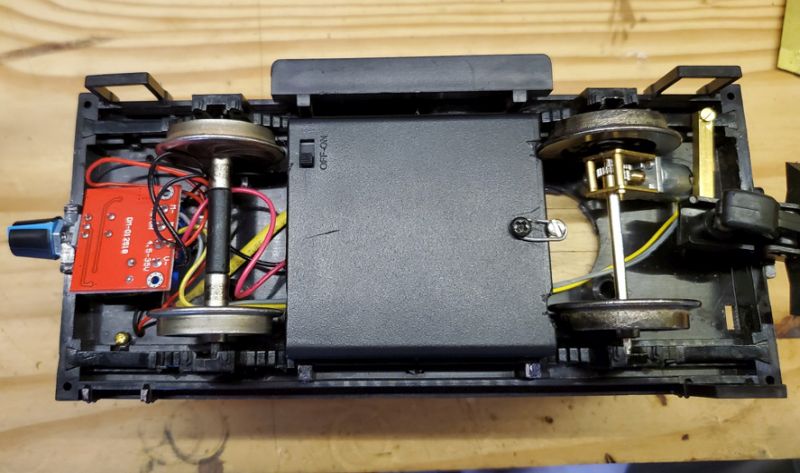
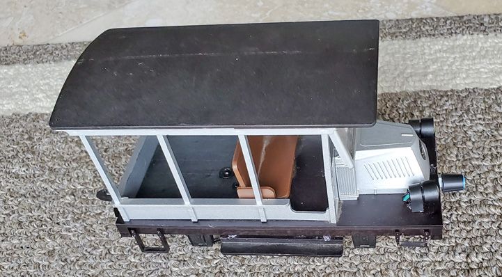
After a frustrating morning drilling the new gearbox I am taking a break to post these few photos in case anyone is interested.
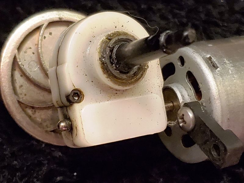
This is the new gearbox without gears loosely put together once I got both sides drilled 3mm. The brass case is sleeved with phosphor-bronze bearings, I think.
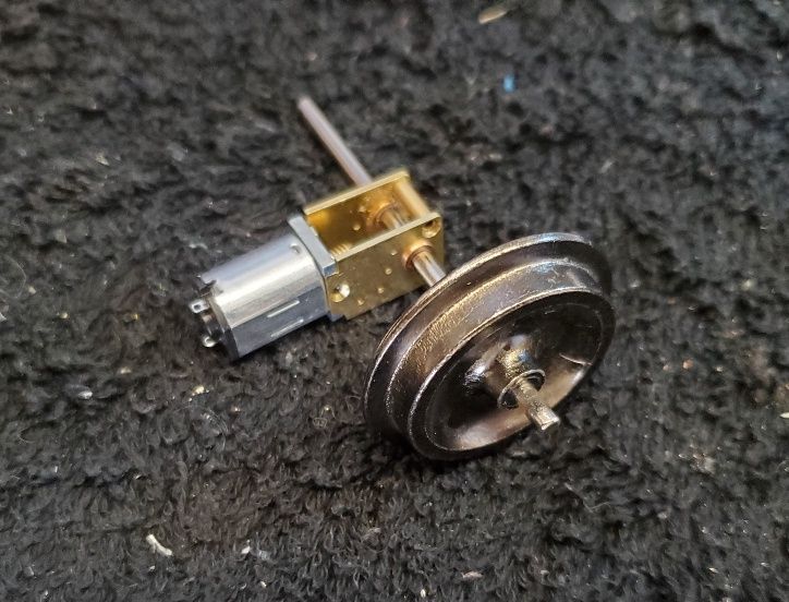
To back up a little, I started this project after noticing some micro-motors with right-angle drives on my favorite chinese website (aliexpress.) This motor, sitting on a small LGB can motor for size comparison, is rated 12V 120rpm and the shaft is spec’d at 3mm, the same as most of our axles.
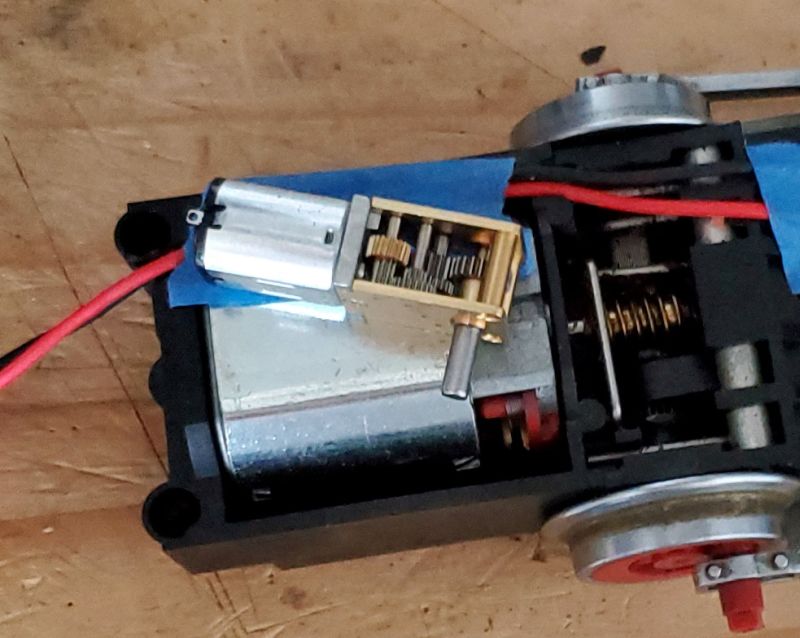
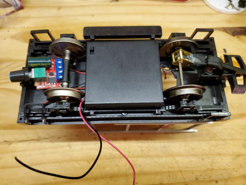
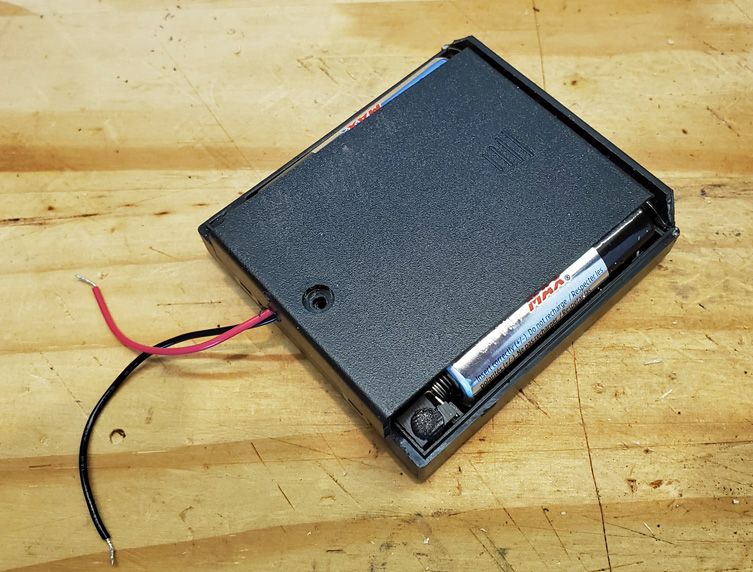
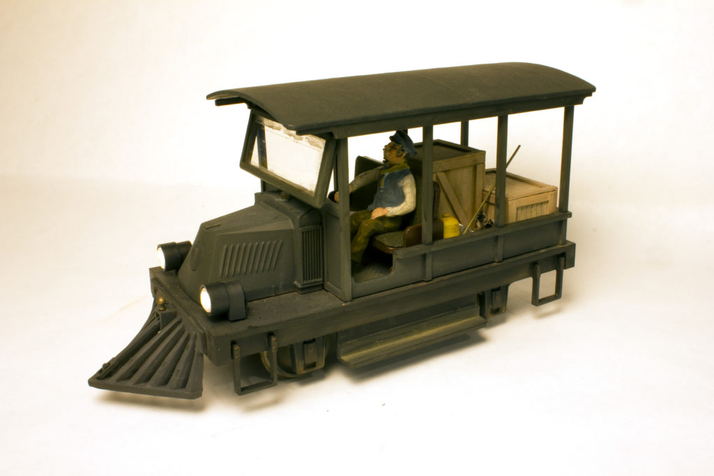
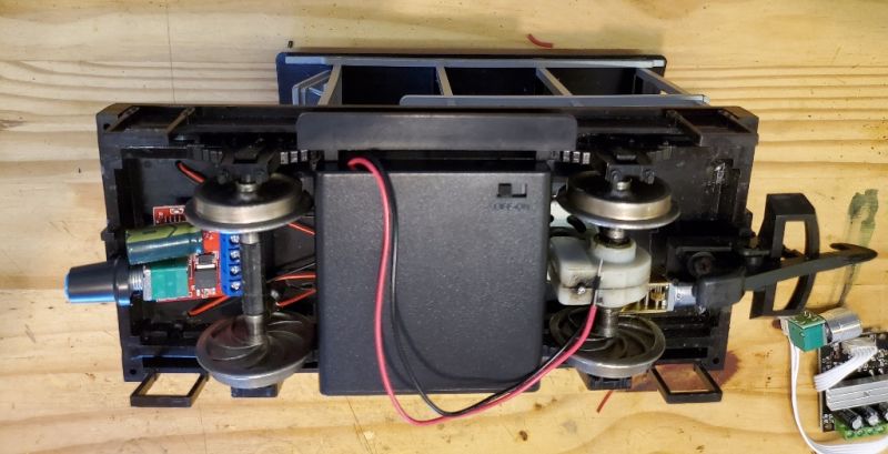
This is the general plan. The weight in the center of the Doozie gets replaced by a 6V “AA” battery pack, and a PWM speed control gets mounted somewhere. The gearbox goes - you can just see the micro-motor under it.
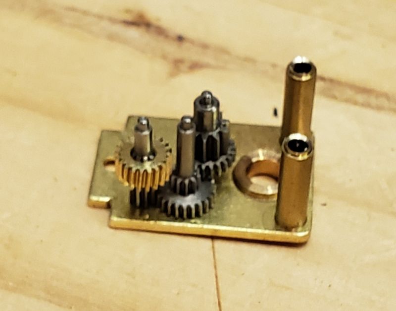
That was the theory. First I had to drill out the ends of the stand-offs/supports keeping the gearbox together at the axle, which means re-tapping them and screwing it together. Then I found that only one side was 3mm - the other was nearer 1.5mm so that had to be drilled. Here’s the geartrain without the final drive gear, which is also not 3mm - more like 2.3mm.
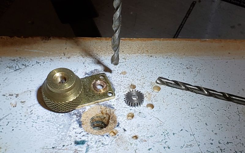
And without a proper workshop, drilling hard materials is tedious. Here’s the drilling rig under my Dremel which is on a drill stand so (in theory) it is vertical. That’s the side plate with the small hole which turned out to have a bearing in it. The knulred knob is a heat sink over a nail dropped into a hole, so if the drill grabs and tries to spin the brass side it doesn’t take the end off my finger. Next to it is the (steel?) final drive gear which has to be drilled out 3mm and fixed on the axle.
I ended up fencing the final drive gear in with some more small brads to stop it spinning, but haven’t yet got the 3mm hole completed as my 3mm drills aren’t hardened steel. Wonder if I have any more somewhere. . .
