Thanks Steve. Not trying to cause you more work. Prices will very much fluctuate, understood.
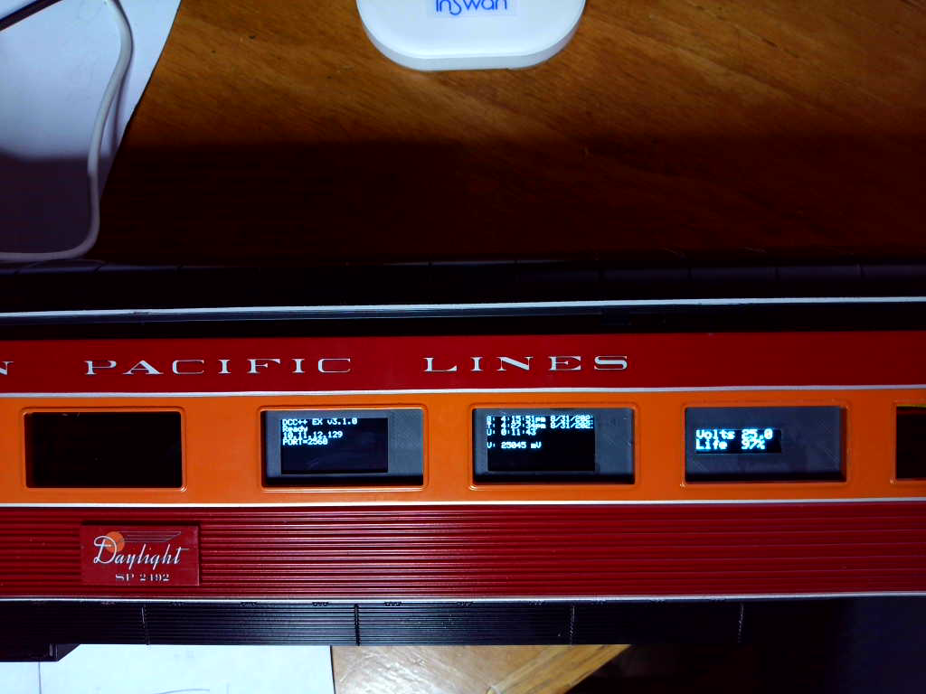
The display panel is printed. It will be exposed thru the boxcar door once I get the boxcar body mounted:
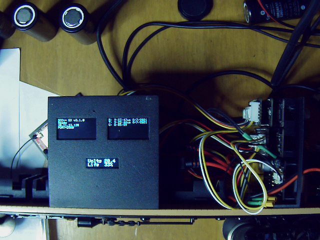
The top left display is for DCC++EX, showing status, wifi address and wifi port.
The top right display is for the diagnostics mcu, showing boot time, current time and uptime.
The lower middle display shows the current battery pack voltage and estimated remaining charge in percent.
It works!!!

MTH G-scale Coastal Daylight #99. set to DCC.
So now I need to design PCBs for the 2 feather connector boards…
Steve said:
It works!!!
MTH G-scale Coastal Daylight #99. set to DCC.
So now I need to design PCBs for the 2 feather connector boards…
Add a few lightning bolts and the quote “It’s ALIVE!” might be appropriate. (Apologies to Young Frankenstein)
Sent to fab:

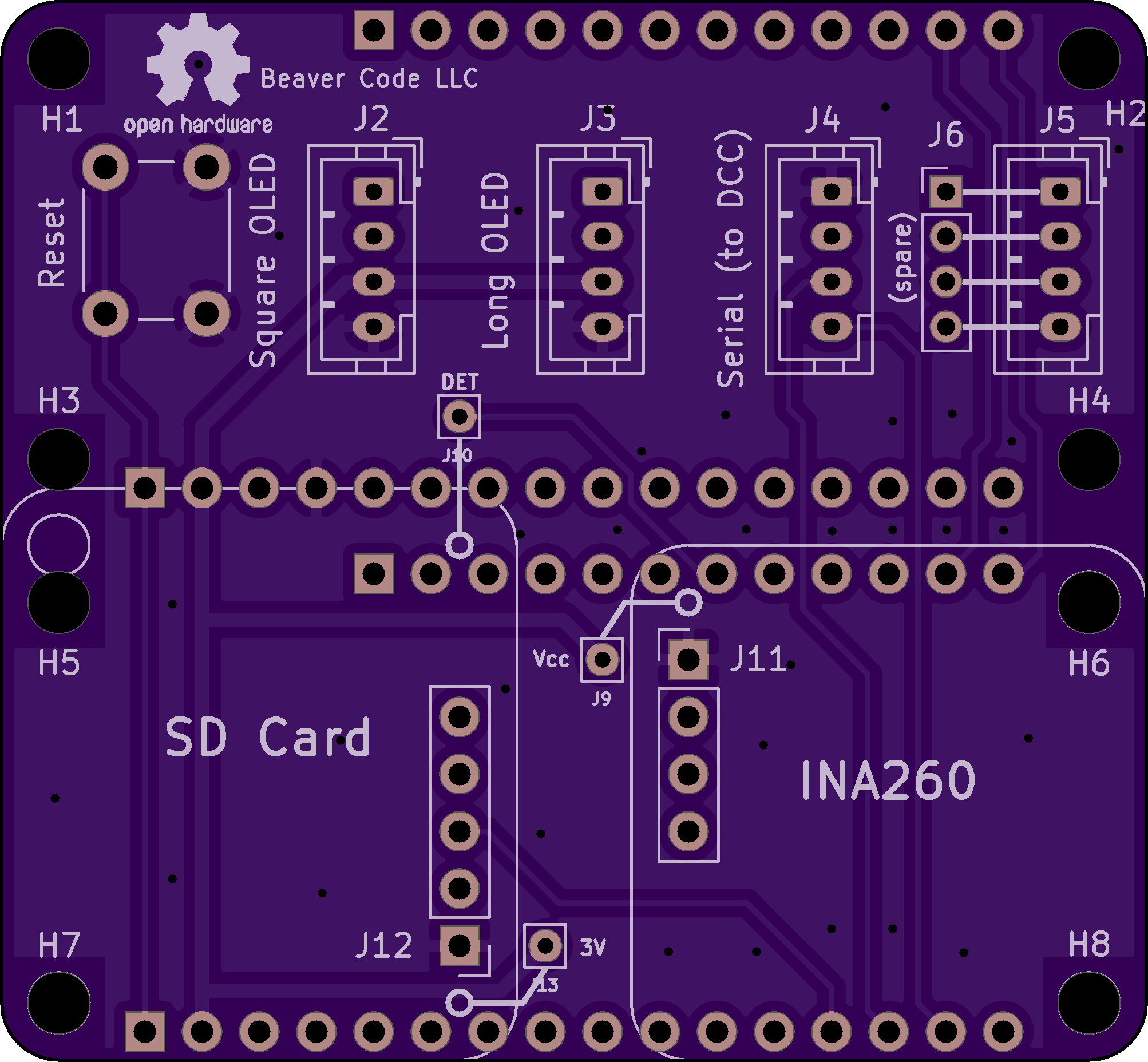
The pc boards are due the 15th.
Started working on deadrail passenger cars for the Coastal Daylight twins:
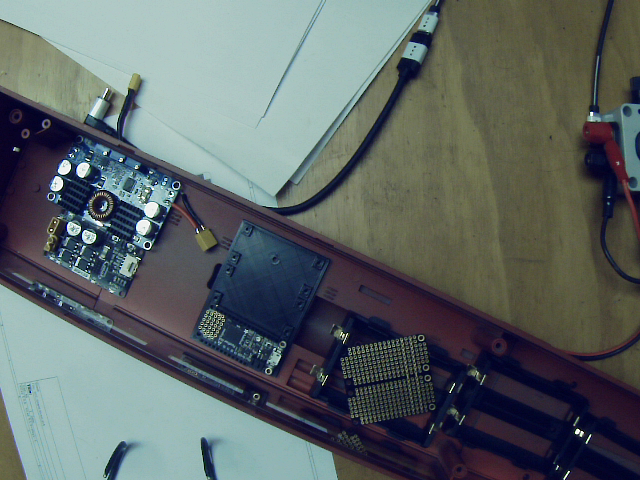
Finished mcu holder in middle, starting on holder for the battery manager and motor board controller next.
A LOT more room in the passenger car vs. the BigBoy’s boxcar.
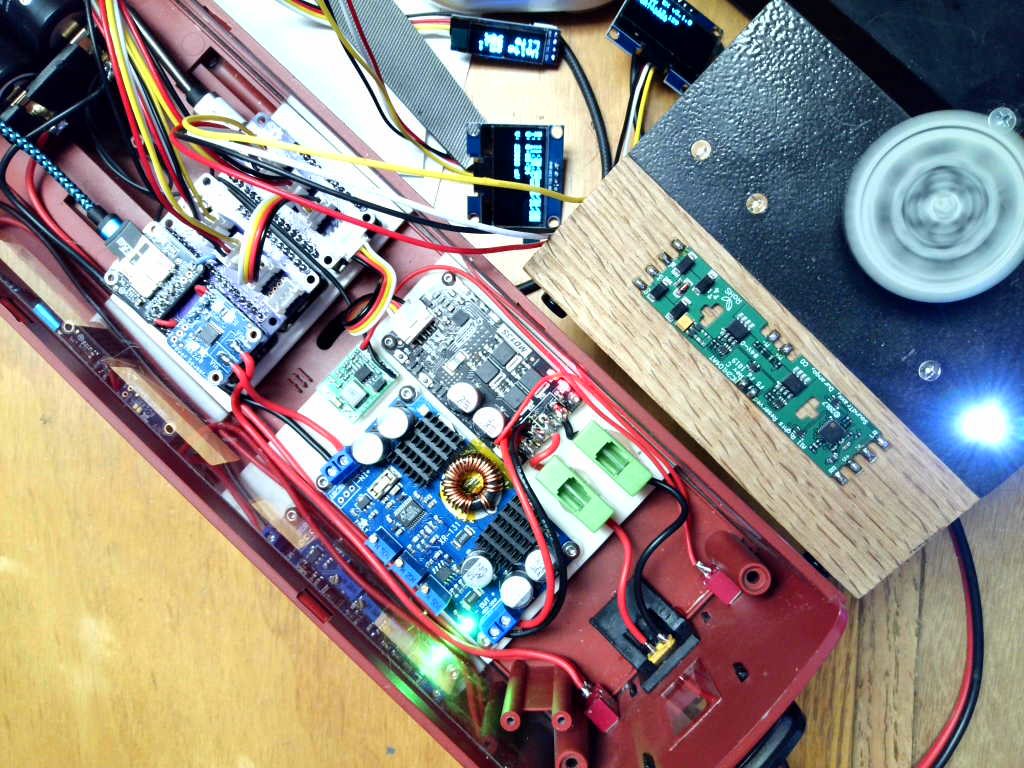
The PC boards arrived today, so I guess I need to put the carrier design aside and get back to the deadrail cars. Mounts for both battery manager and mcus finished and installed. Power switches and external connector installed. Battery holders installed.
Note the module between the mcu mount and the battery holder. This is an opto-isolated 10amp relay board. This will be controlled with an mcu digital pin, and drive a power bus for the passenger car lighting.

Got a new webcam, trying to set it up. So here’s a test picture of the passenger car switches and connector:
PCBs assembled, tested and working, no blue-wires (https://www.largescalecentral.com/externals/tinymce/plugins/emoticons/img/smiley-laughing.gif)

I previously decided to simplify parts by using the Feather M4 for both DCC and diag mcus. This meant I had to place an SDCard breakout on the diag PCB to replace the one that was on the Feather M0 Adalogger. This PCB also holds an INA260 breakout for the battery monitor software.
When I placed my first order for Feather M4s the standard M4 was unavailable, so I went with M4 CAN (CAN bus) versions. Now they are unavailable till end of Sept, so am going back to M4 Express for the 2 passenger DeadRails cars. The parts supply chain situation continues to suck…
Finished wiring, tested, WORKS!
So the next step is to design and print a display holder:
Steve said:
Finished wiring, tested, WORKS!
So the next step is to design and print a display holder:
That’s always the BEST part: It works! (Too many of my projects seem to never get to THAT stage!)
Congratulations!
Display mount installed:
Now to connect that opto-relay and the interior lights.
Heck of a day - smoked an mcu with a rookie mistake…
That set me back half a day…
But I did finally get the lights working:

Some notes on the relay board I am using.
- on amazon: https://smile.amazon.com/gp/product/B0993CX9G5
- it measures approx. 100mA current to close the relay, The feather has a 3.3V regulator with 500mA peak current output.
- it sources 2.2mA when the digital pin is set high to activate the relay, spec’ed max for a SAMD digital pin is 2.0mA.

So there is ample 3.3v supply. But the pin current is too high. There is a 100 ohm current limiting resistor in the input circuit. It’s the part labeled “101” in the above image. It’s located between the input connector (VCC IN GND) and a jumper. Do NOT confuse with the other resistor labeled “102”, which is between the 2nd jumper and the relay. Replace the “101” resistor with a 330 ohm part. This reduces the drive current to 0.89mA, quite acceptable.
Another note. To attach the relay to the diag connector wing I used the spare 4pin grove connector.
I cut off one end and attached VCC, GND and pin 6 according to the standard color code. Just before plugging it in for the 2nd attempt (1st was the time I smoked the mcu/relay!) I noticed the wires on the grove end didn’t match the others on that board. Double checked, they sent me on pack of grove cables with the wires in reverse order on the connectors.
If I had powered it up that way I probably would have smoked a 2nd mcu… Changed pins to proper order on cable connector and all worked.
#4449 is on the road:
The Bigboy REALLY doesn’t like those R3 switches! I cringe every time I run him on the train room track.
His Dead Rail boxcar is complete:
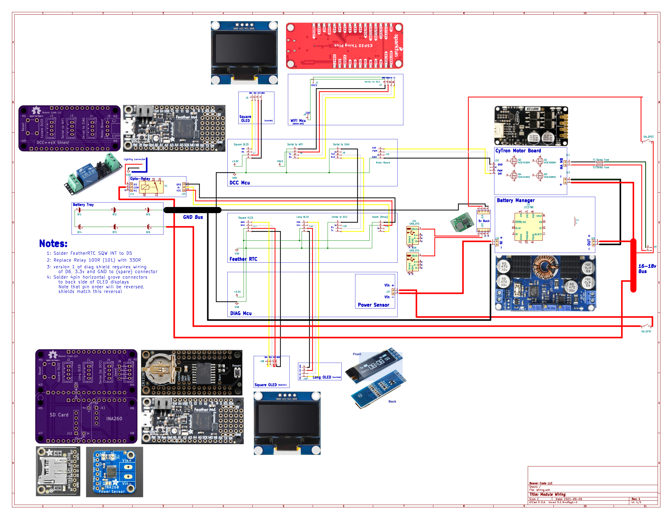
I created a “schematic” that shows the connections of the DeadRail system at the module level:
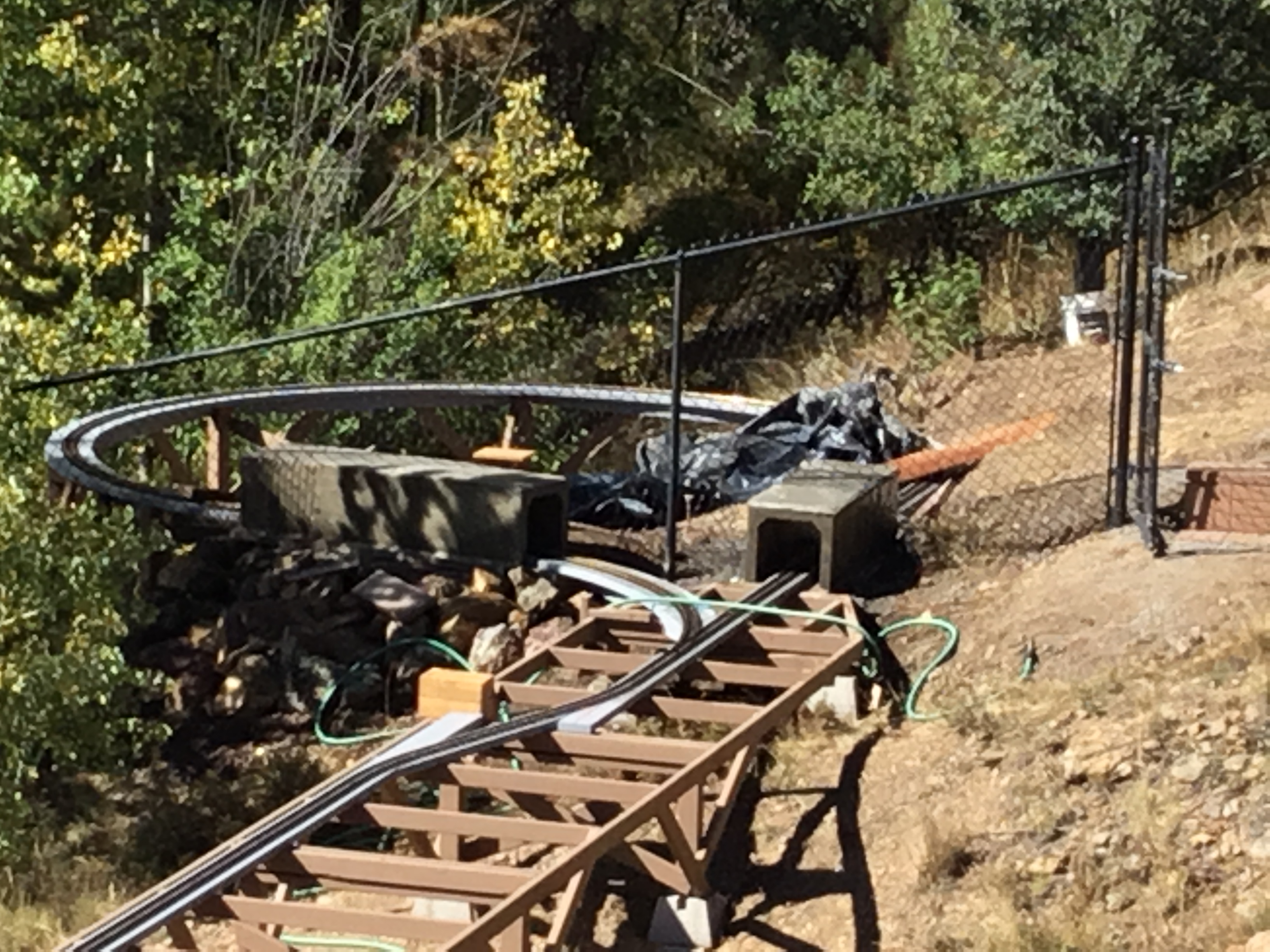
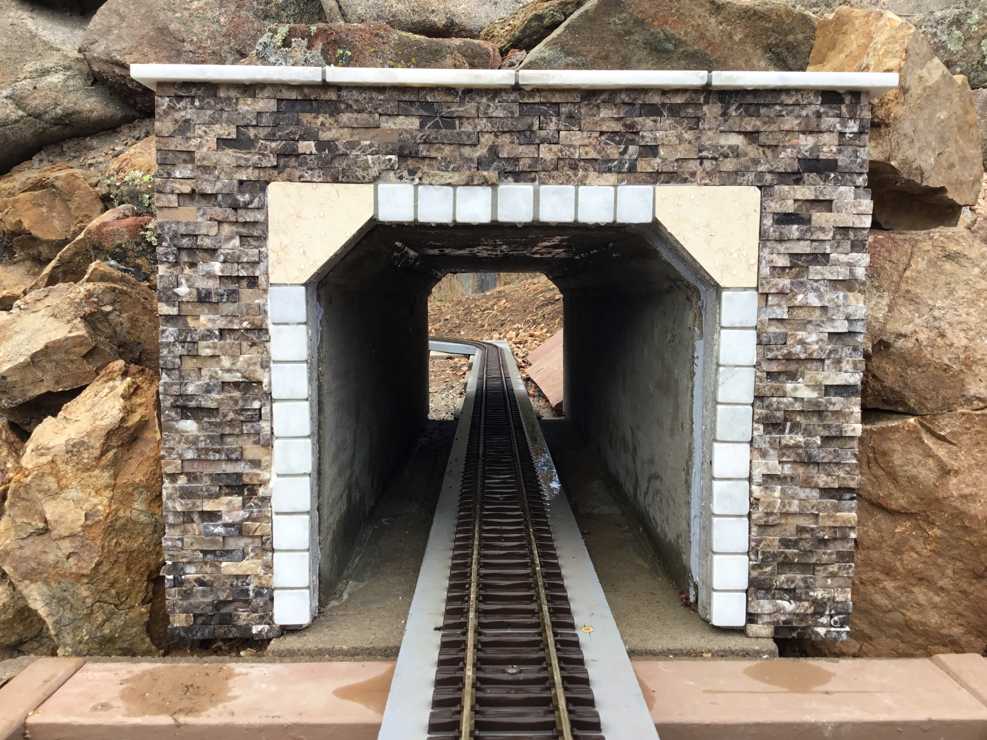
that is a tall antenna? no tunnels?
Jim,
It’s 4 -1/2", built the tunnels extra high knowing they would have to clear antennas: