.Fiends looking for some suggestions on how to have two trains running opposite directions with passing tracks to be able to run them with out having to manually do the switching and stopping. I am not using a command rail wiring system. (in the past I found out the hard way that doesn’t work very well) I am using DC double insulated two cab operation on the main line. I have thought about reed switches, but I have never used them before, and I thought at aristocraft, but hell pretty soon you won’t be able to find parts, any suggestion based upon the old style. Also for those passing tracks, I plan to have the diverging opposite of each other so that the turnout is always set for that direction, when the train comes out of the passing track the turnout spring will allow the train to move right on through, example use two right turn outs. and then two left turnouts. only part of the track that really needs changing as in a reserves loop so to say is the single track they both share. hope this made sense thanks
A magnet on the bottom of the engine can make a reed sensor on the track control a DPDT latching relay and change the track polarity. The LGB EPL drive (12010) with the 12070 attachment can do this.
If you set the stop sections to be fed with a diode, this would automate the trains and only one power pack wold be needed.
you can use either magnets and reeds, or toddalins system. (he calls it B.U.M.P.A.S.S.)
instead of reeds, he uses short isolated pieces of rail, that trigger the various functions.
the reeds are activated by magnets, the contactrails by any metalic wheel. (so, if you use metal wheels on all your cars, i would propose to use reeds)
i am building just now the second layout with just the two directional traffic, you are asking about.
what i do for that goal:
-
chainging the polarity of the wire connections on half of the locos involved.
-
build a loop with two passing sidings. (or more. in my case eight, for four trains in each direction)
-
put springs to the turnouts. (so that the train incoming always goes to its siding, and the train outgoing cuts open the turnout.)
one could operate the turnouts together with the stop-sections by electric switchmotors as well. -
put three reeds or contactrails for each train stop. (one before the stop-section, turning it off, one behind the stopsection, as well turning it off. ((belt and braces!)) and one either directly before, or after the other train’s stop-section. - this needs explanation. see below.
-
give each stop-section its EPL-switchmotor plus additional switch.
-
connect the contactrails/reeds with the EPL-drives.
-
switch it on, lean back and wait for the first spectacular crash.
various explanations:
LGB reeds are expensive and all reeds burn out eventually.(at least, that is my personal experience) so i did open one LGB-reed, brought it to an electronics shop and bought the components for soldering together my own reed-switches.
the placement of the reeds.
if you set up two trains and one passing siding in the loop, (so that one train waits, untill the other has completed the entire loop) you need to plase the “go” reed/railcontact for the westbound train an inch or two before the stop-section of the eastbound - and vice versa. the “stop” reed/contact for each has to be an inch or two out of its stop section. (and, if you want to be secure, before the “go” for the other train, but inside the siding! not on the common mainline.
if you set up two trains with two passing sidings (or 4 and 4, 8 and 8 etc.) both/all trains are running at the same time.
to keep that in motion permanently, the best is, to have one line between sidings significantly longer, than the other(s).
so the other train(s) just stop at the station, while the one on the longer line starts the other train(s) before it reaches its stop-section. - and, the train, just sent off on the long line in the other direction, has to start it, after leaving the stop.
well, at re reading, that sounds much more complicated, than it is!
if you got questions, just ask away!
and here it is much better explained, than i could do it:
http://kormsen.info/lgb-manual.pdf
Chapter “taking control”
You can also have the trains run opposite directions by putting a switch into the engine that reverses it’s current (e.g., Bachmann’s LS/NMRA switch).
I have trains run in either direction using this method. But you have to use care in where you place the reed switches. I have them on both tracks at both ends of my station area and simply toggle the reed at the end that I want to use at the time.
I do build all of my own electronic gizmos to make the trains, and many other things on the railroad, operate as they do. You can see our railroad run at the link. We run seven trains automatically and they will wait for each other where necessary to avoid collision.
http://www.youtube.com/watch?feature=player_detailpage&v=kUFmrN3SQJ4
Good Afternoon Gentlemen. I am using metal wheels, plastic is totally forbidden on the FP & Southwestern. I really don’t want to rewire any of my Locomotives. I’ll be breaking something and with Aristo-Craft gone. Well not sure if you seen EBay people are crazy with their bidding for something I purchase cheap last year. I think I like the reed Switch Idea. But some of the terminology for the names of the reed switches I can remember or you have modify them. I believe I would need the following.
for one siding 2 DPDT reed switches
Some help I’m confusing myself and think anymore
No such animal as a dpdt reed switch, at least on the consumer market.
What you want to do is use the LGB reed switch to throw an LGB (Piko) turnout motor with the supplementary dpdt switch attached to that.
Or, you could use a reed switch and a dpdt latching relay. With the supplemental switch attached to the LGB turnout motor, you create a latching, dpdt relay that just happens to be able to throw a turnout at the same time.
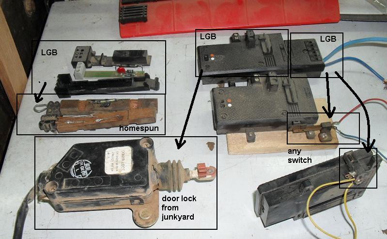
in the pic below:
in the upper left corner is, what i call a reed switch.
it consists of a reed, two diodes and a “thingy” (forgot the name), that helps the reed not to burn shut so quickly.
the upper one is the (older)LGB model.
below it are two of my homemade copies.
on the upper extreme right you see the LGB additional doublethrow switch, that can be driven either by a LGB turnoutmotor, or a signalmotor (as shown).
the reed activates the switch/signal motor, which mecanically throws the doublethrow switch.
one switch needs two different reeds, each with a diode in different direction.
i think, i forgot to mention that this works on AC (14 to 18 volts)
Thank you gentlemen, I’m sure I will be asking more questions coming soon, However isn’t LGB & US products wired differently, kind of confused on that one from whjat I have read in the past