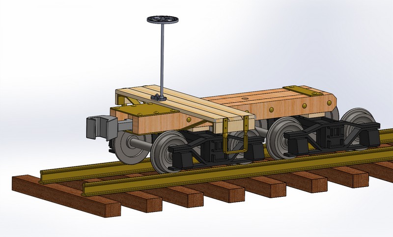
Bob C, and et el… Let me preface this posting by saying, I am NOT an engineer, nor have I taken any classes in structural analyist. Nor have any advanced training whatsoever ever in structural design. Hell i’m just a photographer with very little college classes in anything other then the graphic arts field. That said…
I though that with Bob C’s. posting and such… I would let others in on my thinking as for the designs on my drop center heavy hauler. Please if I make a assumed statement that is incorrect, will someone smarter then me please correct me (encouraged with no hard feelings) and lets discuss the why’s and success…
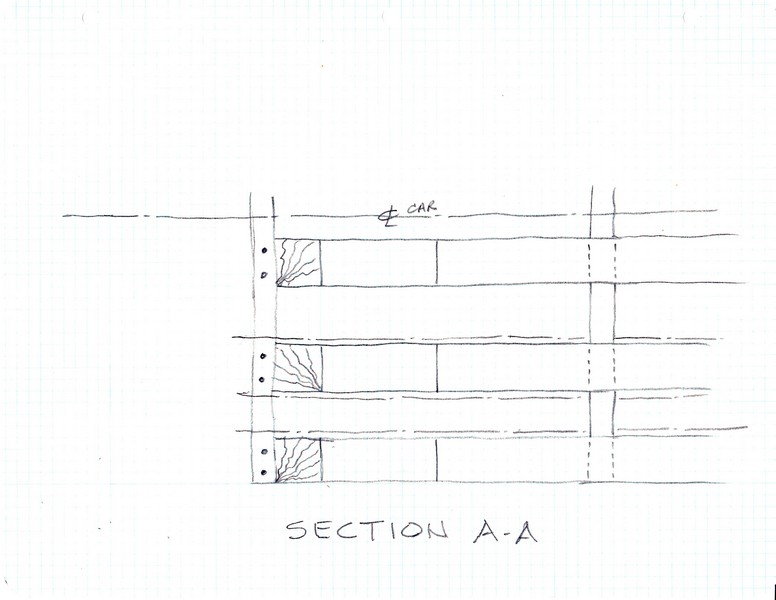
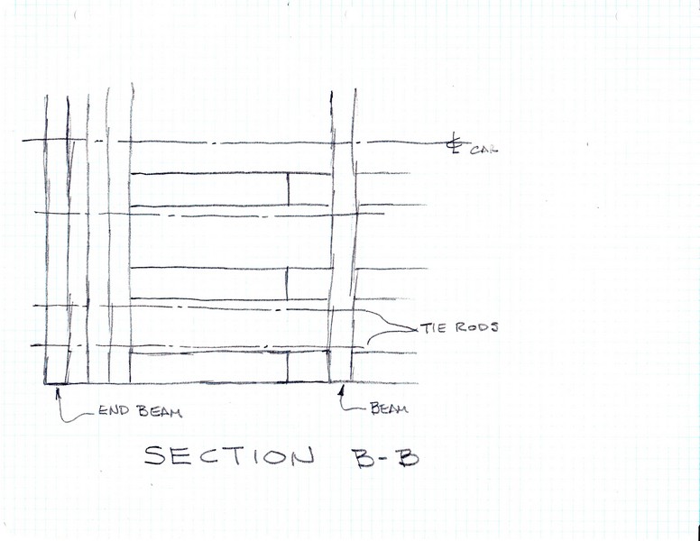
Here is Bobs drawing of his proposed assembly layout. It is actually very similar to my original design. My markups are in red so we ( all of those that want to get into this ) can be talking about the same things. I know that some of my terminology may not be industry correct. So here goes.

First off: The LOAD FORCE is the weight of whatever the car will be carrying… assuming even weight distrubiation across the car. This applies a force that needs to be distributed outwords to the SUPPORT POINTS, which are actually resting upon another flat car. For this discussion we are assuming that this force is constant, equal to the LOAD FORCE plus the weight of the car structure.
To get the LOAD FORCE out to the SUPPORT POINT, the weight must be transmitted thru two joints ( labeled J1, J2 ).
When the LOAD FORCE is applied a vertical sheer force is first encountered at J2, meaning that the joint it trying to be separated (pulled apart) vertically. This same stress is also applied to J1. And then transferred to the SUPPORT POINT. In so doing the force is attempting to bend the J2 joint and decrease the angle and increase the STRESSES at Stress Point S1 therefore causing Brace B to go into a compression status. [ NOTE: Wood beams are strongest under compression as long as twisting and warping of the beam is controlled , and weakest when they are under tension (pulled) ] BRACE A is likewise under compression resisting Stress Point S2 to decrease the angle. STRESS at S3 is neutral being controlled by compressed BRACES A & B.
Now as the train starts to move: [ Note: the LOAD FORCES STAY constant not affected by the lateral forces] The LATERAL FORCES to pull the weight of the car plus the load on the car and the total tonnage of the loads being pulled by the train is applied thru the SUPPORT POINT, and transferred again thru joints J1, J2, and on thru the car body. This LATERAL PULL FORCE attempts to apply stress a S2, by decreasing the angle of J1, which is held in check by the compression of BRACE A. The stress is then applied at STRESS POINT S3 wanting to increass the angle at J1, this increase at J1 also increases the angle at S1, and then takes BRACE B out of compression and puts it into tension. This increases the separation forces at J1. As the forces attempt to straighten out the joints at J1 & J2 and trying to center the forces into a straight line between LOAD FORCE and SUPPORT POINT. All these LATERAL factors are reversed when the train inertia is applied from the rear tonnage when the train stops. Attempting to push the car together, or pull the car apart at J1 & J2 at each end.
Wood beams under tension are only as strong as the joints and mechanical connection holding onto the wood structure. Thickness (size) of the beam, type of wood species, location of the connector and type of connection all come into play as to the strength of the mechanical connection on a Tensioned beam.
To much heavy brainage for tonight. Tomorrow I’ll ( or someone else) get into the design differences and my reasoning between my design and Bob’s.
Dave


