My new project will be four D&RGW 6000 Series (almost) flat cars with various loads. I have taken the drawings from the September / October 1987 issue of Narrow Gauge and Short Line Gazette and generated a set of AutoCAD drawings at 12"=1’’-0". The drawings in the Gazette are at 1:48 (1/4"=1’’-0") so line widths sometimes exceed an inch, so some extrapolation has been done.These have then been scaled down by 1:20.3. To generate a set of drawings to make my cars from, I dimension this last set of drawings in 5 place decimals. I then rounded the dimensions to the nearest 1/32" for making a cut list, included below. I am posting a series of pictures and PDF drawings of my fuxture build so anyone who wishes to use this material can follow suit, or even “scissors draft” their own custom car. The drawings presented in the photos are not necessarily the finished files. As I was working on laying out the blocking for the frame fixture, I came across dimensions I had left out, and cleaned up the arrangement some. Fixture drawings can be found “link here”. If anyone has a set or real 6000 series flat car drawings, possibly from the Maxwell collection, I would not mind adding the information from them.
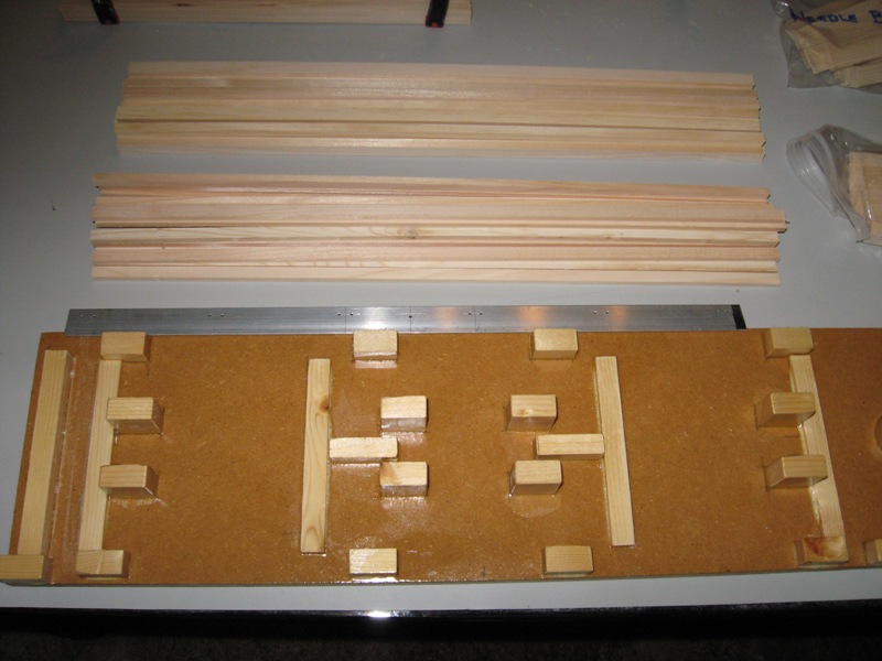
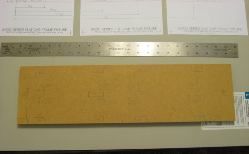
The base for the fixture is a piece of 1/2" medium density fiber board (MDF) cut to 5 3/4" x 21". Photo 1 shows the basic base, and Photo 2 with End Beam and Stringer blocking locations layed out. I chose the MDF material for the base because it is very dimensionally stable, and will take a finish well. I am using a gloss polyurethane finish to minimize the frame sticking to the fixture in the evnet that any excess glue should ooze out and get between the frame and the fixture during fitup and assembly. A coat of wax will also aid in releasing any excess glue.
Figure-01
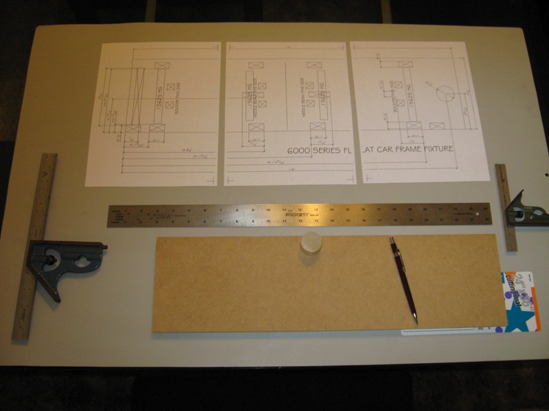
Figure-02
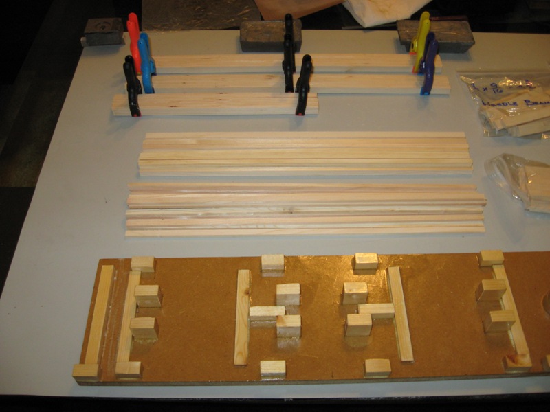
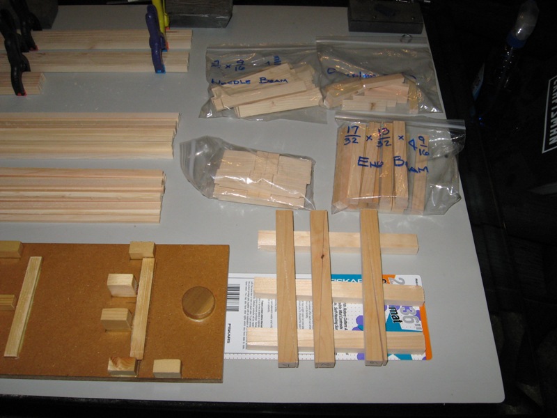
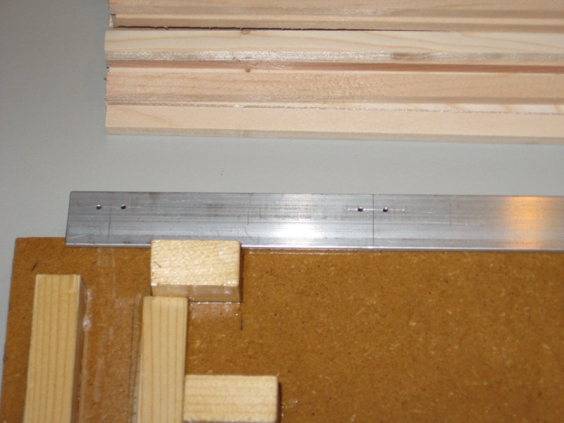
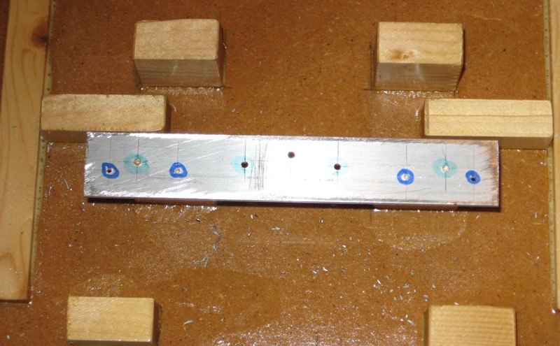
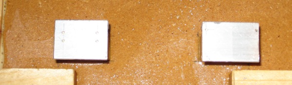
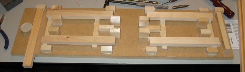
The positioning blocks are scrap pine from household projects, glued in place, held with clamps while the glue sets up. Pigure-03shows the general layout of the blocking on the base board. Figure-04 shows the dowel which will act like a ‘‘3 legged chair’’ when the wedges are applied against the End Sills. Figures -05 thru -07 show some of the progression of adding the blocking to the base. Figure-08 is the completed fixture, ready for finish. Also in this picture are the wedges that will be used later in the assembly portion of the build. More on the wedges and making them later. See the materials list provided in the PDFs for the dimensions and quantities of the individual blocking pieces required. Once all the blocking is in place, and the glue has dried, clean up any excess glue with a sharp chissel to keep all the joints square and crisp. Coat the entire fixture with several coats of gloss polyurethane, keeping any bubbles to a minimum and scuffing between coats with steel wool or fine sandpaper. Once the polyurethane has cured for a couple of days (the humidity in Florida is brutal), give the fixture a coat of hard wax. I use a carnuba car wax. (No pictures of the finished and waxed fixtue yet. Still working on that part.)
Figure-03
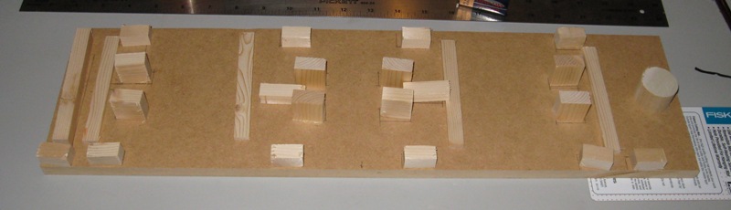
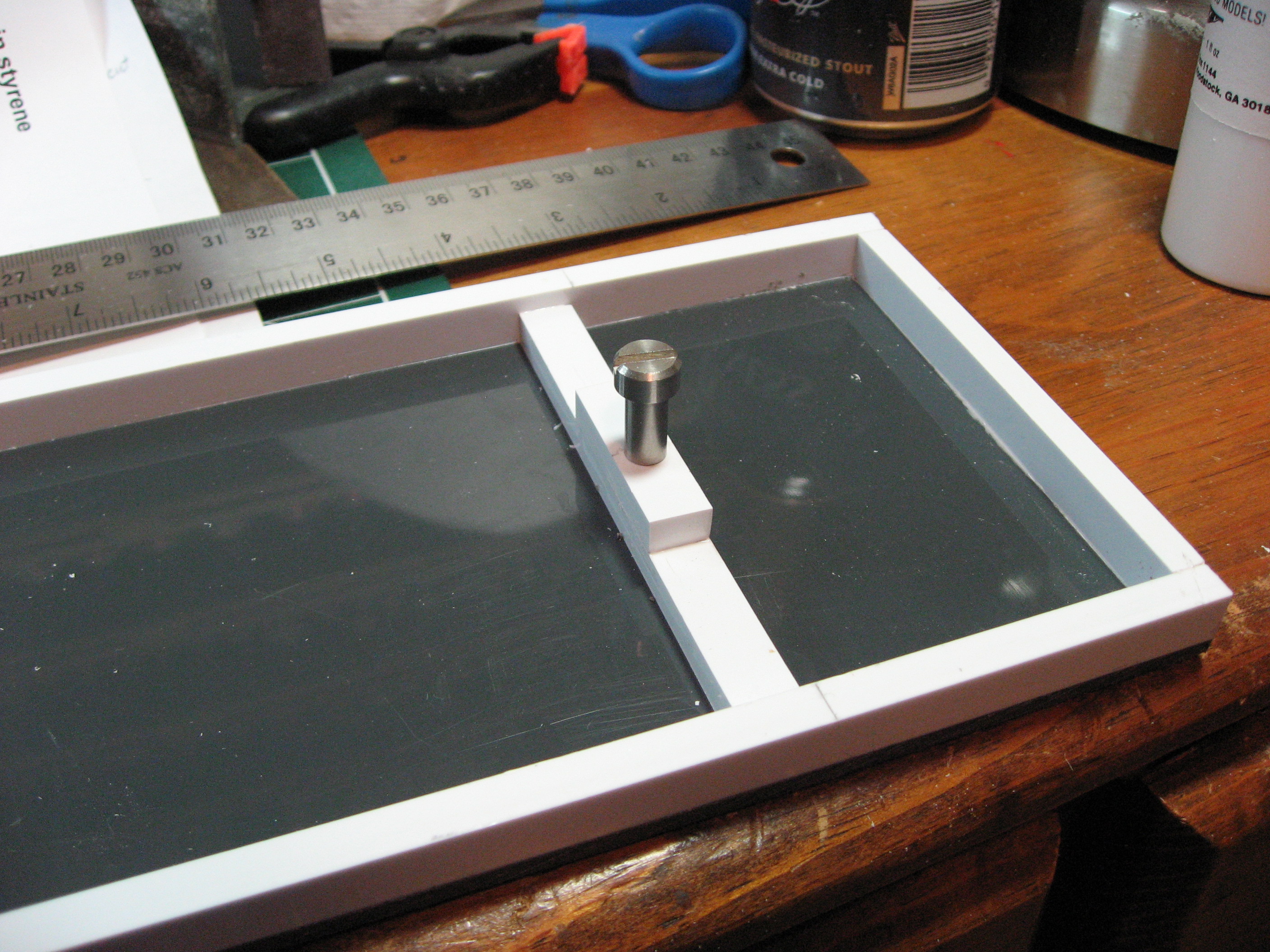
Figure-04
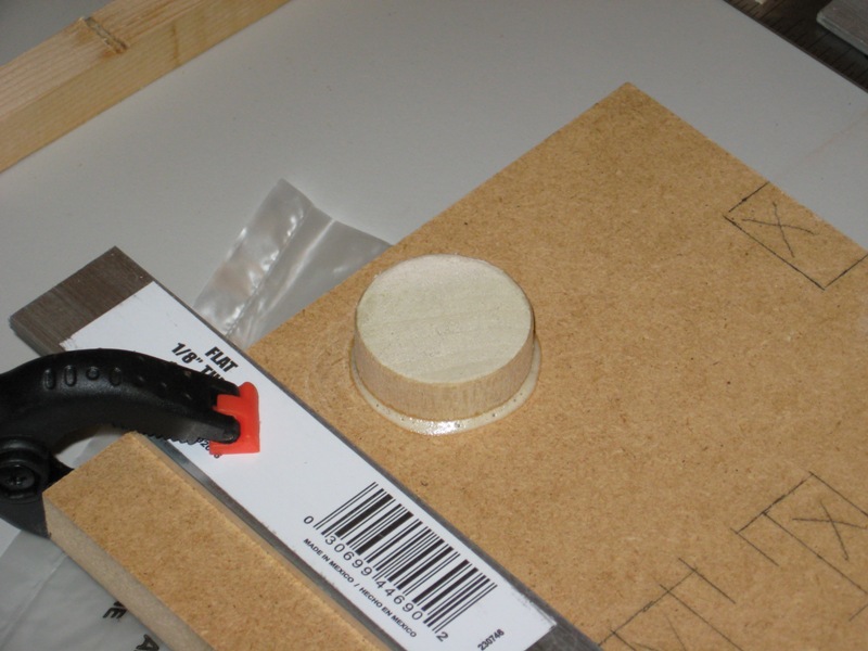
Figure-05, Figure-06
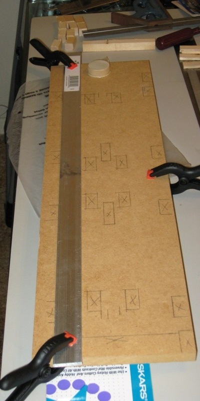
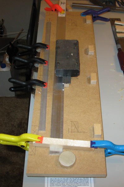
Figure-07
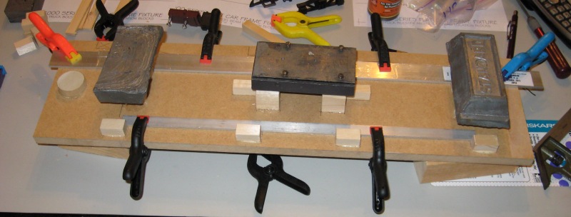
Figure-08
… and the link to the PDF drawing of the fixture for those interested.
https://www.gscalejunkie.com/GeneralPics/6000Flat/6000_Frame_Fixture-.pdf
More to follow in the days and weeks to come.
Bob C.