Large Scale Central

D&RG 315, My week in Silverton

@Ray et al:

For the Osier night shot:

Cannon 5D MkII (full frame)

Cannon 16mm-35mm f2.8

ISO 1250, 30sec, f/5.6 16mm setting.

Lighting:

Whitelightning Ultra Strobs

1- 3200-WS w/ 200w modeling lamp

1- 1600-WS w /200w modeling lamp

Fired remotely via wireless trigger.

315 with two of her younger sisters getting ready for her days work.

(http://i1234.photobucket.com/albums/ff403/dave2-8-0/315463488_zps6dce7bcc.jpg)

Chama at the duel spouted water tank. 1895 C-18 315, 1905 K27 463, 1925 K36 488.

Very early morning light

Great picture. You have captured the beauty of steam in this very nice B&W shot. Thank you for posting.

Doc Tom

Another pic from my week in Chama.

(http://i1234.photobucket.com/albums/ff403/dave2-8-0/RockTunnel_zps7cb2b0ee.jpg)

D&RGW C-18 315 finds the light of day coming out of Rock Tunnel while pulling a string of stock cars up the mountain on the C&TS RR.

(http://i1234.photobucket.com/albums/ff403/dave2-8-0/DesertCurve_zpsf35b67da.jpg)

D&RGW 315 chases across the high desert country with a string of stock cars, with just a few miles to go to reach her days rest at Antonito CO.

Dave,

These shots are terrific. Have you ever considered a career in photography? I think you have what it takes. (just kidding, I know you are a professional) :stuck_out_tongue:

Wow, more excellent shots! Great job!

Beautiful. Love the light and sky in both of the pics. Good job!!!

Tom

Awesome pics, Thanks

Here is another pic from Chama. I drew the long straw and had the 8-midnight shift for tending to 315. All was well and she was being a good girl, so I had some slack time, which means that I set up the tripod and camera and took some pics.

(http://i1234.photobucket.com/albums/ff403/dave2-8-0/315_night-01_zps95e7d33d.jpg)

C&T engines were way hot and the pop-off valves were going off all the time and provided the background steam plume. Exposure was 30 sec, and I added some light to the engine with my pocket flashlight by painting (shining the flashlight all over) the engine.

BTW: Late at night train yards are almost void of people, and you almost have the place to yourself.

Dave Taylor said:

Here is another pic from Chama. I drew the long straw and had the 8-midnight shift for tending to 315. All was well and she was being a good girl, so I had some slack time, which means that I set up the tripod and camera and took some pics.

Great picture. I was wondering what jobs you had to do to tend to a fired up steam engine at night??? Was there a worker posted to each locomotive under steam at night at the engine house??

Thanks for this very informative thread with beautiful pictures.

Doc Tom

Tom et all, The 315 is so different in fire box configuration compared to the K series of engines that the D&S and the C&T run, that we have in the past had problems with the “Local” guys night firing. Having worked with both RRs Night crews. We have had some minor damage to the grates from over size fires in the box.

(http://i1234.photobucket.com/albums/ff403/dave2-8-0/315/photo-08_zpsd3a4c804.jpg)

The actual size is about 18 in wide and about 6ft long. Note that the lower tubes come way down near the grates, and there shouldn’t be a large fire in that area. It can also cause clogged tubes from the lack of draft. With the tapered sides to the box, if you miss with the direction of toss of coal, it slides down the side and piles on the edges, the far edges have no vent holes for air flow, and you get less out of your coal and very hot spots on the grate. We have even had a “local” guy fire on a run, and partially melted a couple of grates ( BTW the grates are very hard to come by).

Because of the issues we have had in the past, the team, has started a program to get team members qualified to fire our own loco and being well trained on the issues with 315s firing to prevent any additional damage.

Bottom line. We have become rather cautious on tending to her needs, we have come to use the gentle approach and not the slam hammering. We watch over her very carefully. After all she is 118 years Old.

Very interesting info, thanks!

For those of you that want to super detail your C class D&RGW locos, or for those that just want to know, or just curious.

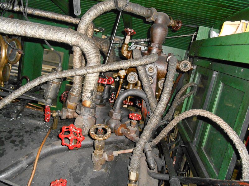
When I started this thread I took some pics of 315s Cab interior. One of the things that dominate the back end of our boiler is the “Steam Turret”. It looks like this:

(http://i1234.photobucket.com/albums/ff403/dave2-8-0/DSCN0034_zpse50a44c7.jpg)

This is shot from the fireman’s side looking across to the engineers side. It certainly is a jumble of valves and piping. What’s it do? And why is it there? One of the First things you figure out about a steam locomotive is, the form of everything on an engine follows a function. There is absolutely nothing on a steamer that doesn’t have to be there to preform a function. The “Turret” is the control center for every thing that runs off of steam on an engine. All appliances are controlled from here.

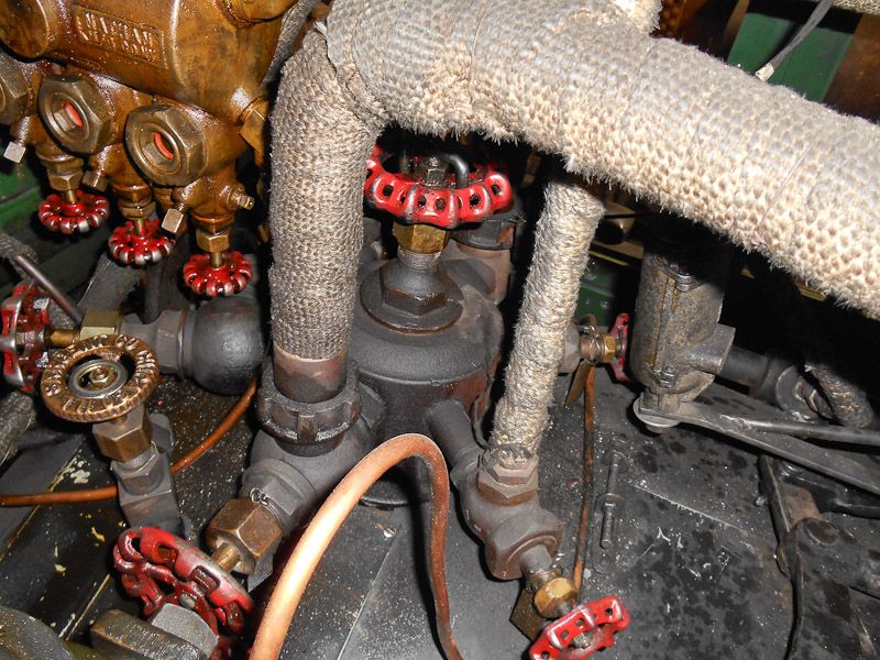
Heres the Turret from the engineers side foreword looking to the rear of the boiler.

(http://i1234.photobucket.com/albums/ff403/dave2-8-0/DSCN0040_zpse118849a.jpg)

Notice the Big Red valve in the center, it’s the “Turret Valve” it is the main shut off valve for the turret. 315s has an external shut off rod that goes thru the cab roof. Its pretty darn close to your lawn sprinkler valve reach rod.

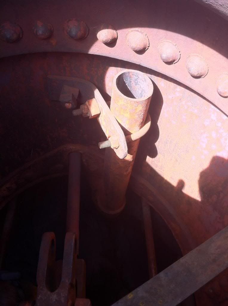
The other end of the valve goes to the Steam Dome as a “Dry Pipe” Here is the other end, looking down into the boiler from the steam dome. Its always above the water level.

(http://i1234.photobucket.com/albums/ff403/dave2-8-0/315/photo-23_zps2ea3ef52.jpg)

Nothing really special, except that it gets its steam from high in the dome, and pipes it back thru the inside of the boiler to the turret valve.

315 has 6 taps (valves) coming off the turret in a radial pattern. Each valve controls a different appliance on the engine. You can see the lines coming off the valves and heading off to there assigned jobs. As the turret and the valves are feeding live full pressure and heated steam to the appliances, they are VERY HOT. Most all are wrapped with insulation (originally asbestos, but now with fiberglass) to preserve the heat energy.
(http://i1234.photobucket.com/albums/ff403/dave2-8-0/315%20Chama/DSCN0036_zpsdd3ef181.jpg)

Note that some are larger then others. I’ll explain what each does as we go around the turret, starting with the valve handle thats pointing to you int the pic.

1st. It’s a smaller one that drives the turbine generator, it comes up and goes thru the cab front where the turbine is on the other side of the wall. There is a regulator in the generator that feeds the steam to generate 32 VDC when the valve is wide open, but you can decrease the flow and slow down the generator and make the lights dimmer. There is a switch box in the cab to turn on the lights and such.

Next around clockwise, is one of two big valves.

(http://i1234.photobucket.com/albums/ff403/dave2-8-0/315%20Chama/DSCN0040_zps1fe98e12.jpg)

It feeds the water injector for the boiler, on the engineers side. Keeping water in the boiler is the most critical thing on a steam engine. If you let the water level get down below the crown sheet… BOOOOM ! It’s so important that it’s required to have two of them so that just in case one goes bad, you can still add water.

You can see it in the bottom right of the view from the engineers side.

(http://i1234.photobucket.com/albums/ff403/dave2-8-0/315%20Chama/DSCN0041_zps4428debe.jpg)

Next around is the valve for the Air Pumps.

(http://i1234.photobucket.com/albums/ff403/dave2-8-0/315%20Chama/DSCN0039_zpsf886ad72.jpg)

It’s the one pointing bottom left. This valve originally feed the singular air pump when it came from the factory. D&RGW "modernized the engine in several steps in the early 20’s and added a second air pump, and at that time added shut off valves at each air pump.

Next around: ( looking from the fireman’s side)is a tap with no valve. It has a bent pipe coming off and running down the boiler.

(http://i1234.photobucket.com/albums/ff403/dave2-8-0/315%20Chama/DSCN0034_zps5dd12843.jpg)

After running down the side of the boiler to the floor and turning to the front of the engine is the valve to control the blower. The blower is a set of nozzles located in the smoke box with the jets pointing up into the stack skirt. When steam is blown thru them they create a draft up the smoke stack pulling hot combustion gases thru the boiler from the firebox. This is basically used when stopped to create draft on the fire and keep it hot when not moving.

Next to the blower tap, is the second injector valve for the fireman’s side. It goes to this.

(http://i1234.photobucket.com/albums/ff403/dave2-8-0/315%20Chama/DSCN0045_zps1e799714.jpg)

One of the two pipes coming up thru the floor is the water feed from the tender, the other is the drain to the ground, thats used to get the injection going. Feed water to the boiler goes out the front, along the boiler to the front of the boiler where it is added at the coolest section, to help keep down thermal shock.

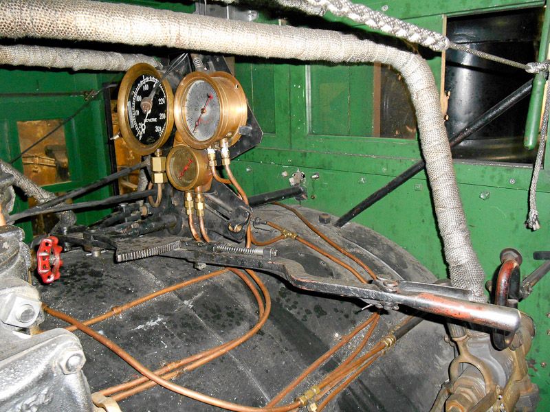
And the last one, that you see going up and to the right, goes to the “Lubricator”

(http://i1234.photobucket.com/albums/ff403/dave2-8-0/315%20Chama/DSCN0039_zpsf886ad72.jpg)

The lubricator is the big brass thingy in the top left. The lubricator is used to inject an oily stream of steam into the cylinders for lubrication. Ours has three taps that are controlled by the valves on the bottom. A drip of steam oil is inserted into the flow of steam and sent to each cylinder via a small pipe that runs along the boiler inside the shell and into the top of the valve box. The third tap goes to the Air pump feed line to lubricate the steam feed side of the pumps.

And thats all there is to it. Now who’s going to model that mess?

Dave Taylor said:

Tom et all,
Because of the issues we have had in the past, the team, has started a program to get team members qualified to fire our own loco and being well trained on the issues with 315s firing to prevent any additional damage.

Bottom line. We have become rather cautious on tending to her needs, we have come to use the gentle approach and not the slam hammering. We watch over her very carefully. After all she is 118 years Old.

Thanks. The picture and explanation answers why the locomotive needed the “night shift.”

I am learning a lot about the care and feeding of these wonderful steam engines.

I also see why they are so “labor intensive”…then and now.

Thank you again for all this great information.

Doc Tom

Looks like a plumber’s nightmare…:wink:

All I can say is WOW!! Thanks for the excellent explanation of the many pipes inside the cab. I had a vague idea but never got such a simple and easy to understand explanation. Thank you Dave.

We are all living vicariously through you and your pictures.

As far as modeling it. I plan to with my Q537. You can get all the major appliances from Ozark or Precision Scale. Next is making all the piping. Now I understand all the functions, I will be able to make a better model.

Fantastic photos and explanation of the cab piping and valves. :slight_smile:

Fantastic photos and explanation of the cab piping and valves. :slight_smile:

Great shots Dave!

Found a few minutes to edit a couple more shots from the “Great Chama Experience”

D&RGW 463 pulls a mixed freight across Cascade trestle in the early morning light, about 2 miles from Osier on the C&T.

(http://i1234.photobucket.com/albums/ff403/dave2-8-0/315%20Chama/463CascadeTresle_zps01b52dc9.jpg)

I’v only seen a few pics of this phoniomon. D&RGW 463 blows a couple of perfect smoke rings in the early morning light as it approaches Osier station on the C&T.

(http://i1234.photobucket.com/albums/ff403/dave2-8-0/315%20Chama/463Smokerings_zps9281824f.jpg)

I have no idea how or why this happens. I really wonder what the physical properties have to be to do this? Any ideas as to How or Why?