That would actually be quite easy to model. Just get a good photo of it and print it out onto self-adhesive vinyl, then apply to a piece of styrene, Sintra, or brass. That’s how I did the plywood patch on this old door:

.
That would actually be quite easy to model. Just get a good photo of it and print it out onto self-adhesive vinyl, then apply to a piece of styrene, Sintra, or brass. That’s how I did the plywood patch on this old door:

.
Ray You crafty little bugger!
Hired by the D&S to host ( put on) the night photo shoot for the winter photo special. Shot at the D&S roundhouse.
RGS Goose 5, and D&RGW 473 hot.

Shot with my iPhone, minor adjustment in Lightroom.
Dave . . . great photo ! (http://www.largescalecentral.com/externals/tinymce/plugins/emoticons/img/smiley-smile.gif)
Nice!
It’s late and Im tired but here is a iPhone shot from tonights Durango & Silverton Winter photo special night shoot I put on.
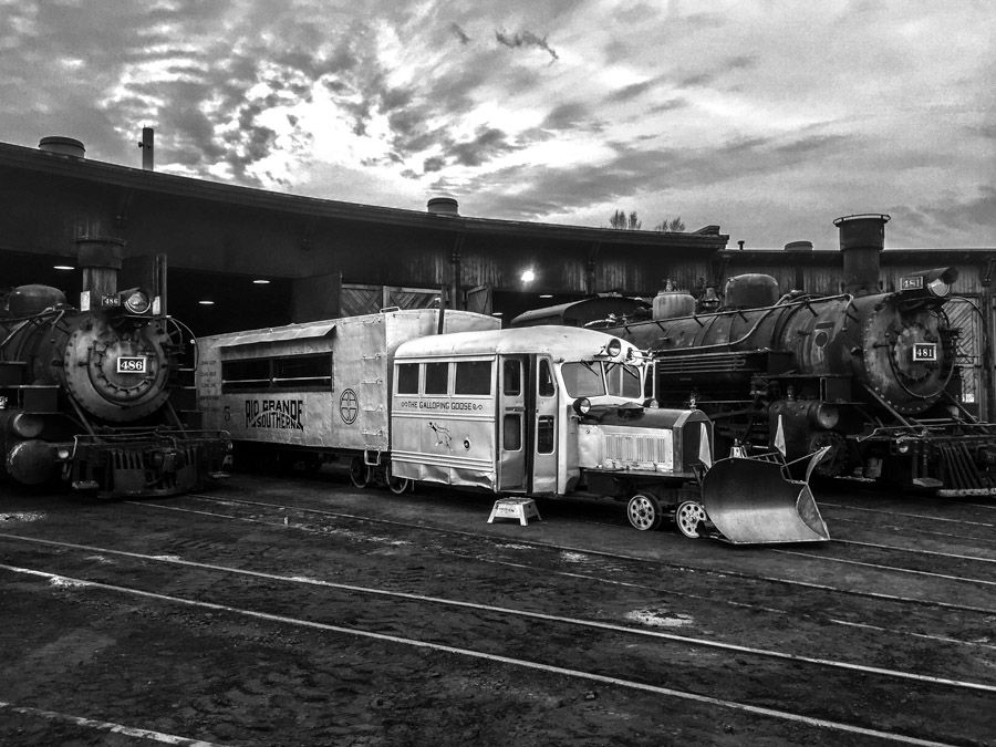
Enjoy…
Dave Taylor said:
Enjoy…
I am…(http://largescalecentral.com/externals/tinymce/plugins/emoticons/img/smiley-wink.gif)
Opening Day Celebrations on the Cumbres & Toltec Railroad
Here is a link to the opening day for the C&T with a special 315 dinner train, and a concert with a John Denver tribute.
http://cumbrestoltec.com/opening-day-celebration-315-dinner-train/
Schedule early as it is expected to sell out.
and as an added bonus I will be crewing on the 315
Made the 3hr drive over to the Cumbres & Toltec, Antonito Engine House to start the first of several work days in preparation for 315’s annual inspection.
She turns 122 years old this year, and celebrates her 10th anniversary of her re-birth in 2007. Wintering over in the Antonito Engine house.

She shares the engine house with D&RGW 463, and the recently acquired 168 ( a class T12, 1888 Ten Wheeler )
Since 315 will be the Opening Day star this year, And we are planing special tributes thru the summer, we will be going thru the mechanicals and the glamor before we show her off this summer.
With it being 10 years now since we brought her back to running, she will get attention to the general appearance, Come spring we will do a complete scrub down of the whole engine and touch up of the paint and re-coat the smoke box and all the high lights. Most of the photographers prefer that, “Working everyday road grime” look for realistic freight photos, She will be dressed up in her finest for passenger service for the start of the year. She did run passenger service for a number of years on the D&RGW, mostly out of Montrose, Salida, Ouray, Ridgeway CO, and also on the RGS when she was leased to them.
Starting the prep on the maintenance that we need to do for this year. One of the issues we had was a slapping of a loose bushing on the engineers side, on the main rod pin. This is the pin that connects the front of the main rod, and the crosshead to the steam piston. We started to hear a tapping late in last years runs, and the CMO (Chief Mechanical Officer) for the C&T, and our CMO inspected and deemed it fine to run, but it should be looked it before this years runs.
Here is the PIN, with the keeper nut, about 3 1/2 inches across. We have already removed the safety plate that keeps it from turning, and the grease button.
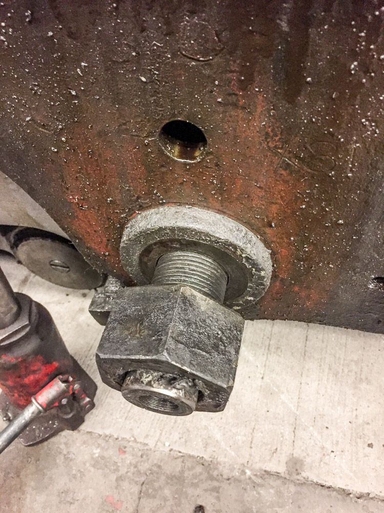
To remove, First we support the main rod, and loosen the screw set pin that holds the bushing wedge in place.

We have moved the loco, so that the driver spoke is aligned, so there is space for the pin to clear as it is pushed back to clear the crosshead. Good hearty pop with the double jack and luckily it came loose on the first swing, there are horror stories of what have had to be done to get these pins out…
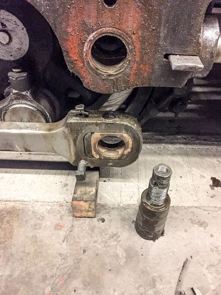
Pulled the nut and washer, pushed the pin out the back, and dropped the main rod.
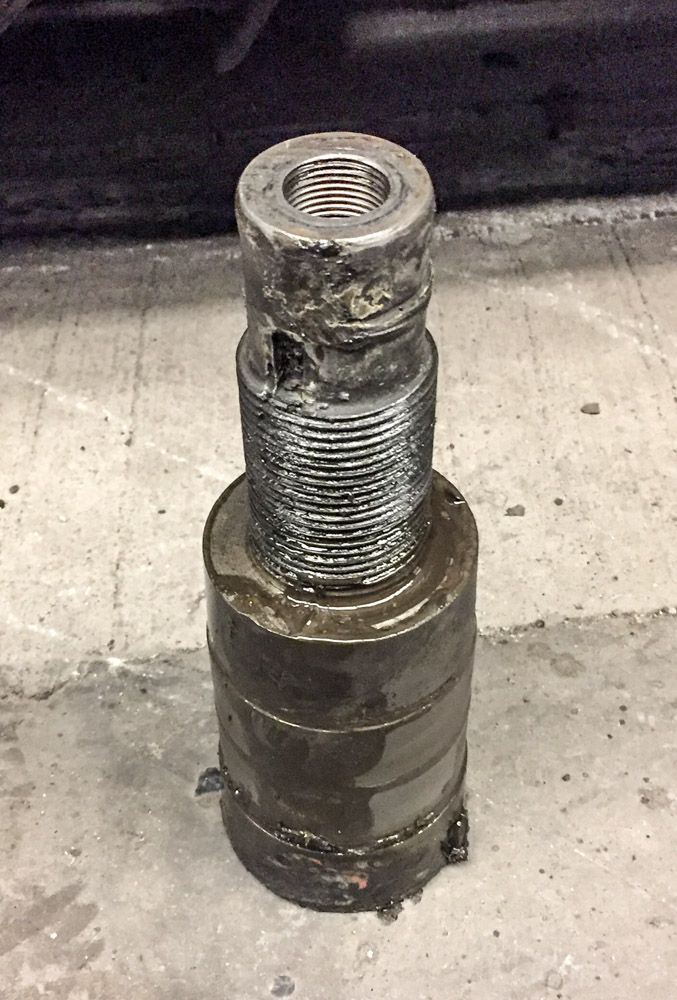
And the PIN. Greasy, grimy work. NOTE: notice the ridges around the pin. When I first saw this I was really worried that we had worn such grooves in the pin. Not so. its made with a taper to the pin and to the crosshead, and a flat surface in the middle for the bushing surface.
To better clarify, I drew out a sectional drawing cutting thru the center of the pin. NOT to scale, and I exaggerated the taper for clarity.
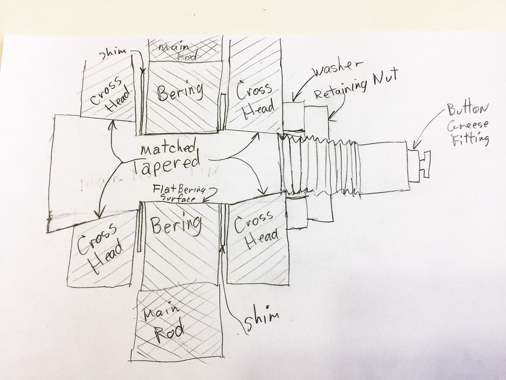
I also left out the internal grease passages for clarity.
Next up: we remove the bushing.
Is this a true “napkin drawing,” or did you cheat and use paper? (http://www.largescalecentral.com/externals/tinymce/plugins/emoticons/img/smiley-cool.gif)

Where did the slop occur?
Bearing (mechanical) (notice the spelling)
From Wikipedia, the free encyclopedia
A bearing is a machine element that constrains relative motion to only the desired motion, and reduces friction between moving parts.
Grease
From Wikipedia, the free encyclopedia
Grease (lubricant), a type of industrial lubricant

Oh, good. Joe knows how to use Wikipedia, copy and paste. Will wonders never cease! (http://www.largescalecentral.com/externals/tinymce/plugins/emoticons/img/smiley-surprised.gif)(http://www.largescalecentral.com/externals/tinymce/plugins/emoticons/img/smiley-laughing.gif)
Interesting Dave. Are you talking about the bushing on the main rod that gets removed next?
Steve Featherkile said:
Oh, good. Joe knows how to use Wikipedia, copy and paste. Will wonders never cease! (http://www.largescalecentral.com/externals/tinymce/plugins/emoticons/img/smiley-surprised.gif)(http://www.largescalecentral.com/externals/tinymce/plugins/emoticons/img/smiley-laughing.gif)

Bearings are designed to fail first, because they can be replaced. The slop occurred between the bearing surface and the pin.
Wow Joe, way to go.
John
John Caughey said:
Bearings are designed to fail first, because they can be replaced. The slop occurred between the bearing surface and the pin.
Wow Joe, way to go.
John

@ Steve F. That is drawing version revision 1.2.0, as I kept tearing the napkin with the pencil, and the further along in the drawing upped the “got to keep it factor” until I gave up and started anew.
@Rich Yup, stayed tuned.
On to the beAring ( happy Joe? ) removal. Now this bearing was new made when 315 was rebuilt in 2007, and as such it was not split ( cut into two halves ), but machined to fit the pin.
This is the Main rod with the bearing in it just as we dropped it out of the crosshead, after removing the pin.
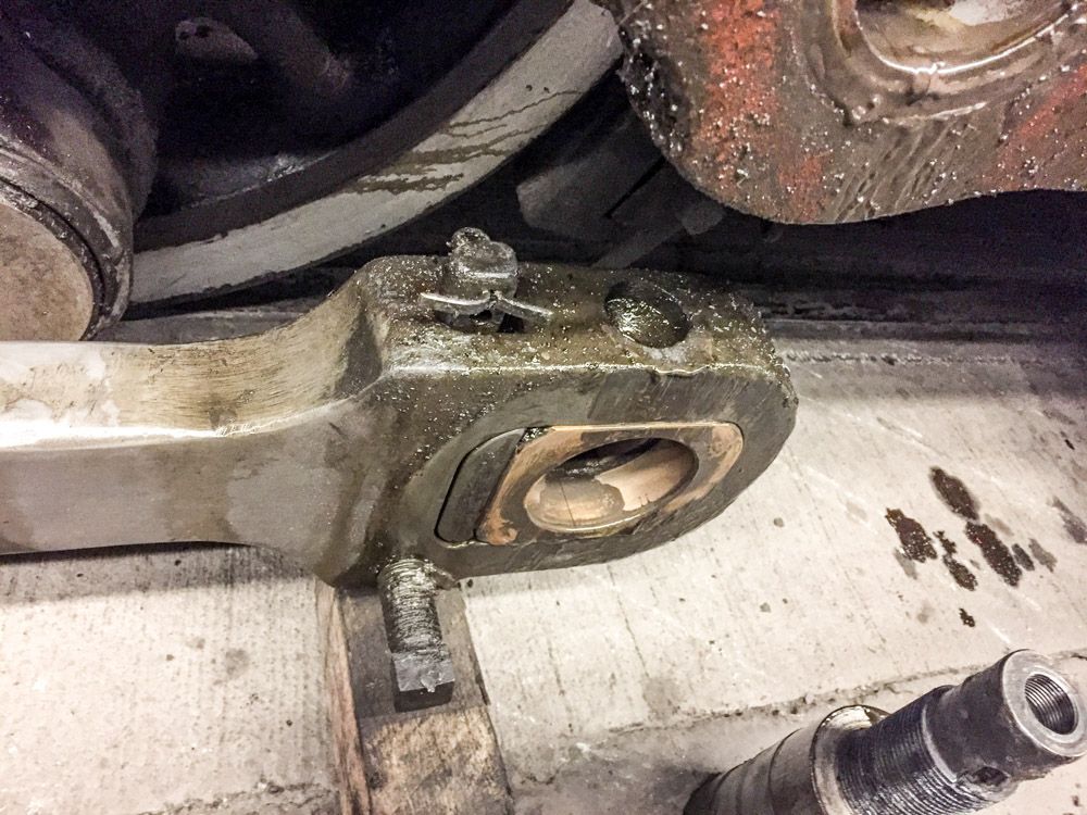
You can see the 5 main parts of this end. 1 - Main Rod, 2 - Bearing, 3 - Bearing Block, 4 - Bearing adjustment Wedge, and 5 - Wedge Set Screw.
Here is another drawing to help clarify how this all goes together. Cut through the center of the rod end.
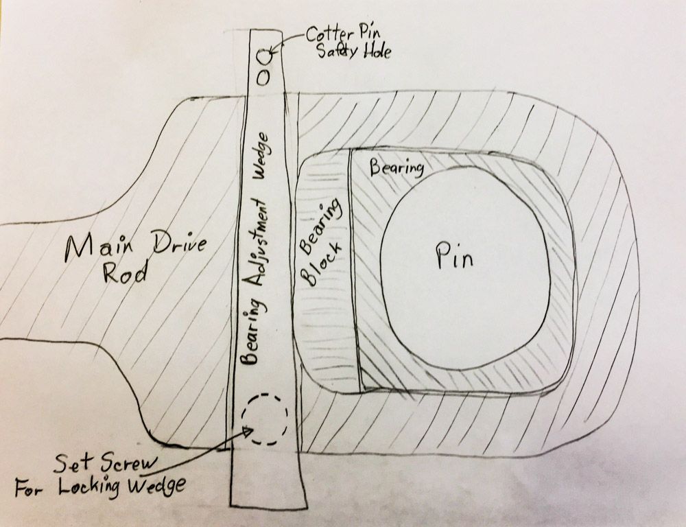

To remove the Bearing and Bearing Block, we start by loosening the Set Screw on the Wedge (FYI that square nut is about 1 1/8 inch across ). Remove the Safety Cotter pin at the top of the Wedge. Engineering Mystery #1, The wedge is tapered, with the narrow end to the top, and the wide end to the bottom. This goes against most reasoning , as if there is a failure of the retaining system, it allows the wedge to fall out completely. No inherent safety built in. Gravity ALWAYS wins!! Drive the wedge out the bottom.
The wedge as removed,
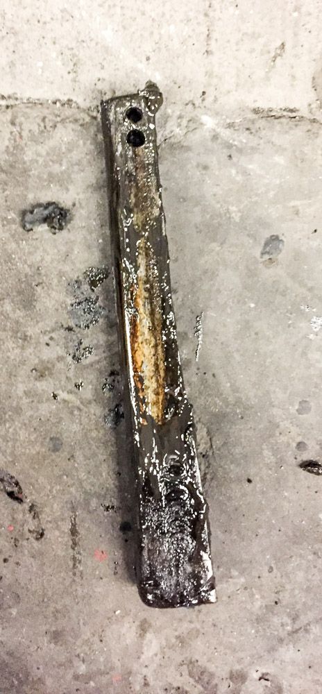
It is hard to notice, but the wedge is worn on the face that presses on the Bearing Block, and it is also bent in the center. A new one will be machined to replace this one.
After the Wedge is removed, the bearing and the Bearing Block, just slides out.
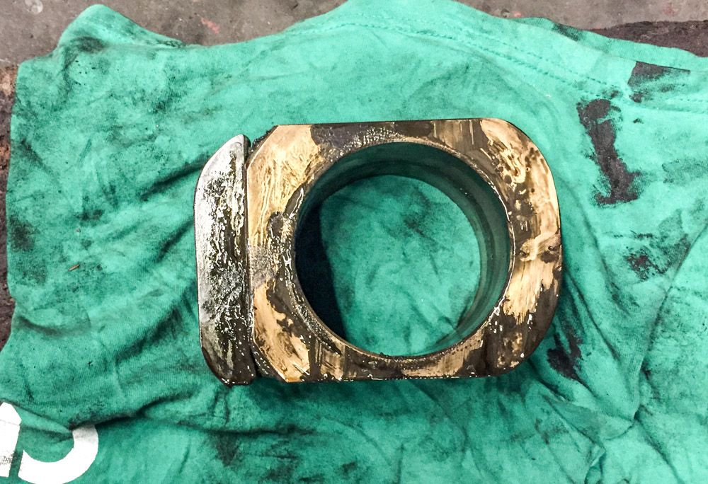
BTW: The brass Bearing is about 4 inches thick were it rides on the pin. About 5 inches tall ( as looking at the photo ) and about 6 inches wide ( L to R ).
In this photo, note that the side of the bearing block that rubs against the wedge, is worn with a groove in it.
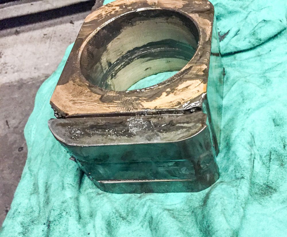
We will be machining a new Bearing Block also.
SO, what was the cause of the “Slapping” sound as we ran? We believe two fold, 1st was the Bearing Adjustment Wedge had come loose, or worn down, and allowed the whole Bearing and Bearing Block to move or slide within the Main Rod with each stroke of the driving pistons. This caused a pounding on the Wedge, and accelerated the bending of the Wedge, and caused excessive wear also, Both actions compounding the problem .2nd was the excessive wear on the Bearing Block, adding to the “Looseness” of the entire Bearing system.
How we going to fix the system? The Main Pin is OK, and will be polished and re-used. We will make a new Adjustment Wedge, and a new Bearing Block. As for the Bearing, we will split the Bearing, and re-bore to fit the pin diameter.
Checking the wedge tightness will be given a high priority in our daily maintenance procedures. Hammer tapping will NOT be allowed on this part from the top of the pin, only from the bottom.
UP NEXT: some tips on timing.
Thanks for the explanation, Dave.
All very interesting . . . . . . (http://www.largescalecentral.com/externals/tinymce/plugins/emoticons/img/smiley-smile.gif)