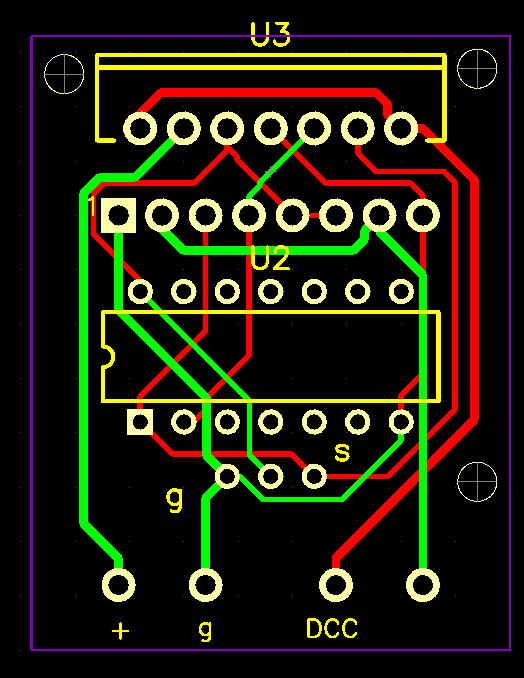
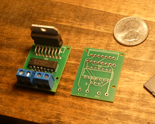
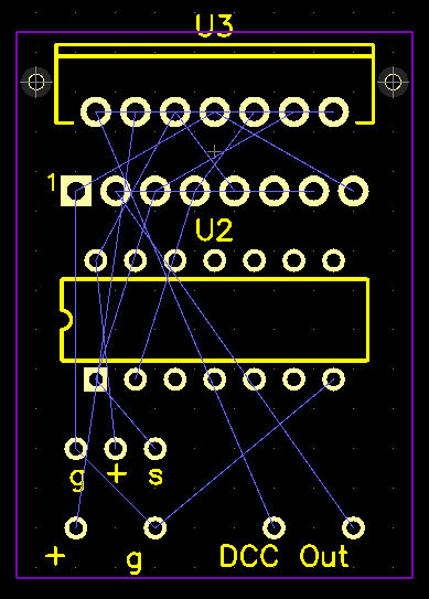
OK, I’m no electrical engineer, but I’ve finally been making progress on an electronics puzzle that’s been nagging me for some time. So for better or worse, I want to share what I’ve learned.
I’ve had a switch machine project on the burner for a couple years, and the prototype worked fine. Even brought it to the D&B. But I needed to miniaturize it, and got stuck on the circuit card.
Dave Bodnar’s boards are beautiful; and he told me he used PCBWay.com. Thanks Dave for all your tips!!!
However, I’m a mechanical guy, working in a 3D CAD package (solidworks) and AutoCAD. And I’ve learned that PCB (printed circuit board) manufacturers only accept proper electrical engineering PCB (“Gerber” or similar) files to do their thing. I’ve also learned that professional packages are either very tough to learn (for a non-sparky), or expensive, or both.
Now, I can make DXF files all day long, but no manufacturers accept them. And I didn’t know why. But several board makers, that supply their own version of PCB design, do accept DXF as “footprints” for the board. That is, borders and holes. Unfortunately, the output is proprietary, and you pay through the nose for that particular service.
This post is about how I was finally able to bridge that gap.
First off, my board is highly bounded by the surrounding geometry, and packaging the components hasn’t been easy.
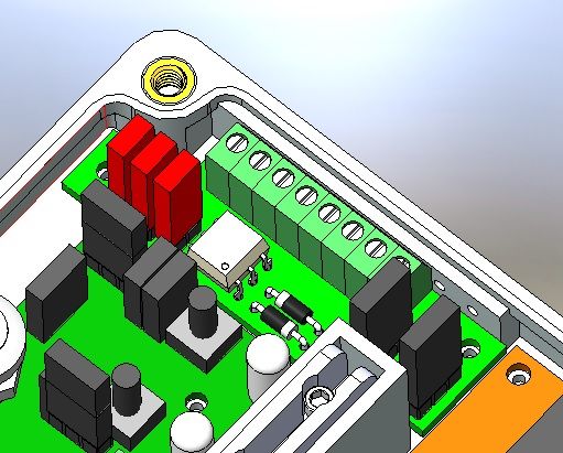
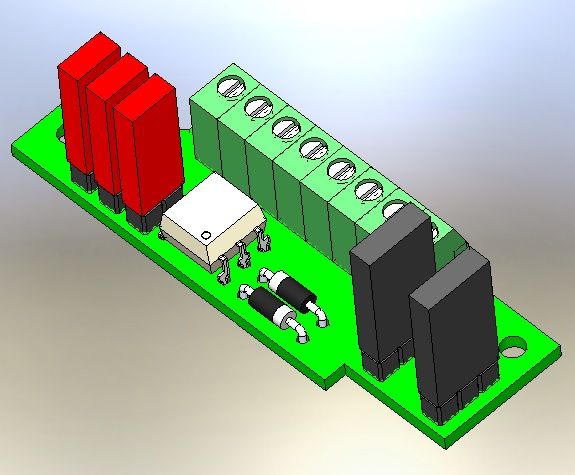
The circuit is simple, and the board is mainly power distribution with a little signal wiring thrown in. Here’s the populated board.
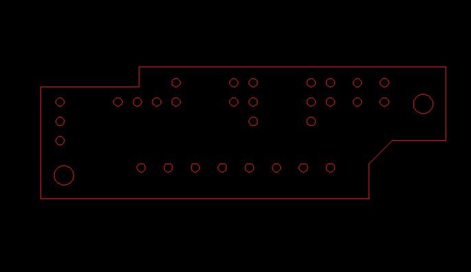
The easy step was to export the board’s geometry to a DXF file.
I hunted for software that accepted DXF, and installed and tested it, only to find that the format was proprietary, the board expensive, and the output wasn’t the Gerber industry standard. So I couldn’t use PCBWay, or sources like that.
But after several gyrations of this, I finally found the key: DesignSpark. DesignSpark PCB is FREE. You have to register, but that’s all. It imports DXF for board footprints, and exports to the industry standard formats.
Here’s the PCB design after importing my DXF, converting it into a “board,” parking the “pads” on it and running the “traces”. I’m over-using the quotes here, because these are the kinds of terms I’ve had to become familiarized with.
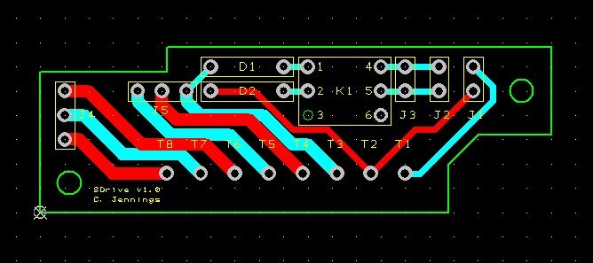
The export function of this software generates the many industry-standard files required for a PCB. For example:
- Top documentation (the board, in green here)
- Top copper (topside conductors, shown in red)
- Bottom copper (bottomside conductors, shown in blue)
- Top silkscreen (what’s printed; in yellow here)
- Top copper resist (not shown; automatic; all that green stuff)
- Bottom copper resist (ditto, on the bottom side)
That’s why DXF or similar CAD files won’t work for this: the layers are in different files, with their own metadata requirements.
All these files are zipped and uploaded to PCBWay. A few 24-hour cycles have passed, while they (in China) found my flaws and told me about them. I fixed, and re-uploaded. And the board is finally passing!
I’m not ready to order quite yet, because I want to breadboard some other stuff and do more testing. But this run-through is telling me that these PCB’s can be had for around 80 cents each, plus S&H of around $9 via “e-packet”.
Probably not gonna rock the socks of a lot of people here, but as a geek I was too excited not to share.
Finally, you folks who do know all about these sorts of things, please share your insights and improvements to all the above!
===>Cliffy
![]()

