Cliff,
You see the guy taking a leak off the 13th St. connector?
insanely would be the word.
not only about half a dozen doubleslips, some Y-switches, some normal ones, but look at the simple crossings: from nearly 90° down to about 20° every possible angle waits for handlaying.
not to mention the 100’ by 100’ room needed in largescale, a Harley’s worth of track, the dozens of switch- and signal-motors, a bucket full of reedcontacts, a mega control-panel, an electrician, a woodworker, a welder/solder - and lots of time…
shudder
That’d better not be you, Rooster!
Maybe a smaller scale, then…
impossible.
how to detail the guy on the 13th St. connector?
1 Like
Seems like this is the perfect project for our Overachiever, Cliffie.
Over here we have the Bronx Terminal.
1 Like
See? This is daunting enough for me, Pete. I cannot imagine doing work like this.


1 Like
I think you mean Overthinker, Lou. 
This might tie BD up for a year or two once he buys the yard next store to get ur done. 
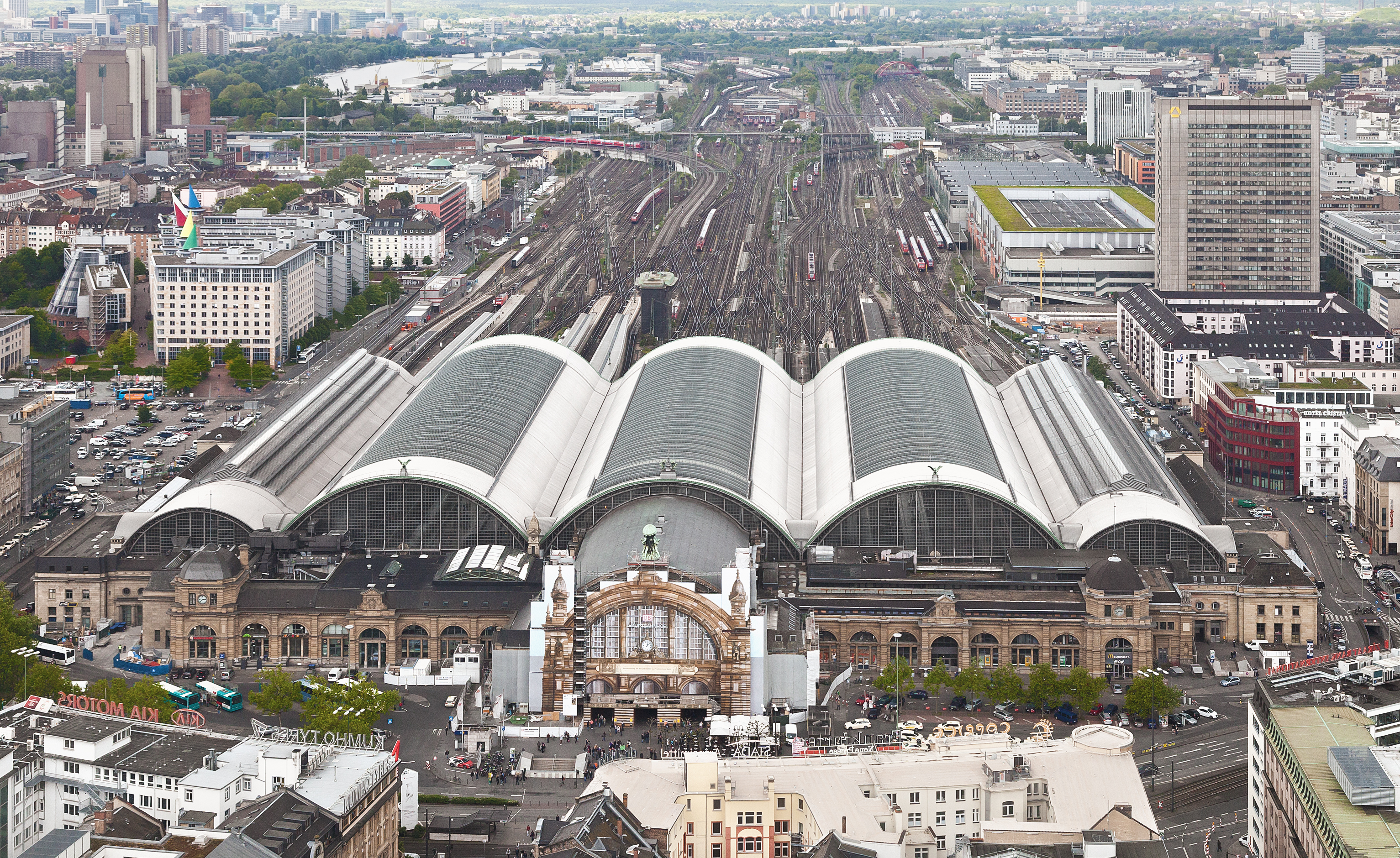
This photo popped up when I was looking at something else RR-related. The shot I am used to seeing! Note there are 3 locos smoking away.

1 Like
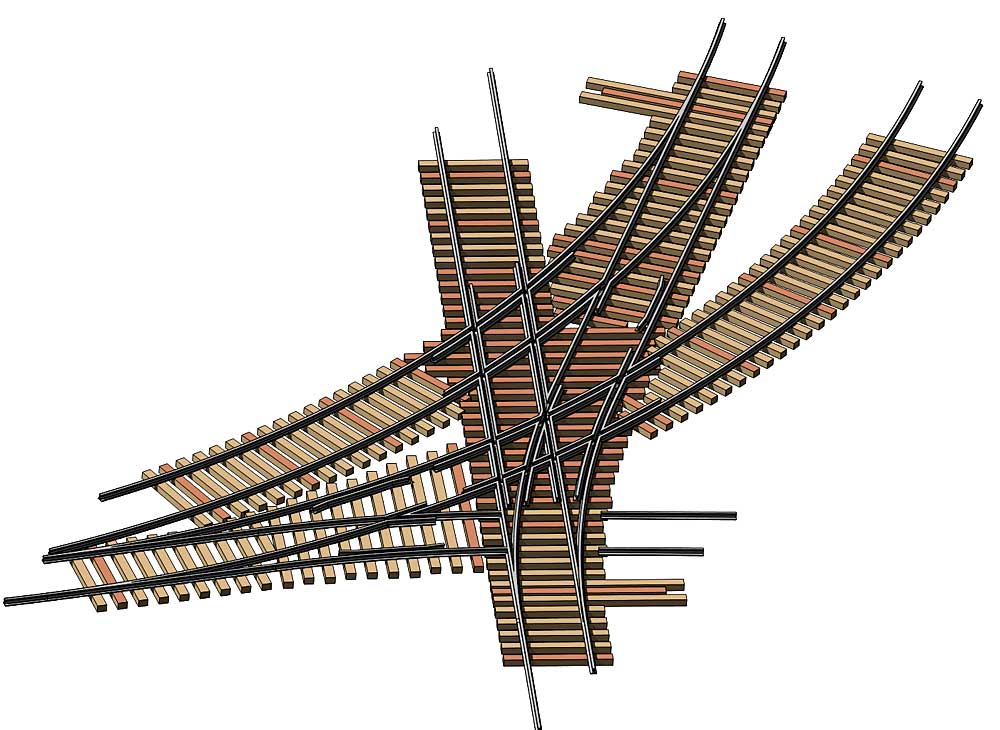
I am intrigued by one set of turnouts on the righthand side of the photo of the Tyne bridge end. After enlarging the turnouts they are the most complex ones I have ever seen outside of the newest high speed ones.
For starters they are two curved turnouts that overlap with each other. When you blow up the photo they become even more interesting as where they overlap each other they have 2 separate components that must move in opposite directions to set which of the two curved turnouts points is being used to control the track orientation. It would be interesting to actually build such a beast.
Stan

2 Likes
By my evaluation, Stan, it looks like if a train is coming from the left-side of the tracks (green line in image below), it could either continue or take a tighter curve right. Whereas, if a train comes from the right of the frog (red), it can only “keep left” of the second frog. I say this because I only see one point that seems to move (yellow circle). Please correct me if I’m missing something!
Photo for clarity.

John, you are only missing that there is a crossing in the middle with movable ‘frogs’. You’ll note the far point/switch is set for the curved route, and so is the crossing. I suspect they are interlocked so that, to set the near point to the curved option, the far point must be switched to straight, and then setting the near point will flip the crossing frogs.
1 Like
Ahhhhh, wow! Yeah, I looked at it, but didn’t think it could move. Thanks for the correction, Pete!
John
I circircled the 4 moving sections of the turnout pair.
There are two sets of points (one for each curved turnout) circled in Red.
As Peter has pointed out, where the rails cross in the center there are two movable sets of rails rather than fixed frogs (shown in green. The interlocking that controls this set of turnouts would also be interesting as it appears that only one of the three possible routes through both turnouts is active at a time,
In the photo the top set of points together with the center moving frogs are set to allow a train to go from the line that the top set of points is on to the right hand side of the lower track. To go to the left hand side of the lower track you must switch both the top points and ensure the lower points are set correctly
To have the lower turnout control the flow to the top right hand track both center movable rails must move and then the inverse to the above works.
A very complex set of space saving turnouts.
Stan

2 Likes
I wonder how truly difficult it was to maintain all of these moving parts for this junction. This one portion alone is mind-boggling to me! Thank you @Stan_Ames and @PeterT for the clarification.
The “throat” of the station tracks was always a place to find complex trackwork.
So, Stan, when can we expect to have to switch this at Steige?
Bob
Interesting thought. While the actual configuration in the photo is rather long and overly complex, the space saving concept they were trying to solve triggered an idea.
This complex combination of turnouts is not all that different in concept from a crossover in that only 3 possible routes can go through it. One key difference from a traditional crossover though is that there is insufficient clearance through the turnouts for any two routes to be active at a time. This provides a real space savings.
On the SJR&P west of Zephry I have a new section going in with tight clearances. Instead of narrowing the path next to this area, a series of two turnouts with the frogs right next to each other should work. Only one train can be routed through any of three possible routes through these two tightly coupled turnouts at a time but that restriction is in itself interesting as well…
So off to the design table we go.
Stan