Bill,
Thanks. Will do. Toy trains of any sort beyond “Thomas the Tank Engine” push toys are rarer than hens’ teeth out here. I’ll keep my eyes peeled at garage sales.
Eric
Bill,
Thanks. Will do. Toy trains of any sort beyond “Thomas the Tank Engine” push toys are rarer than hens’ teeth out here. I’ll keep my eyes peeled at garage sales.
Eric
Update:
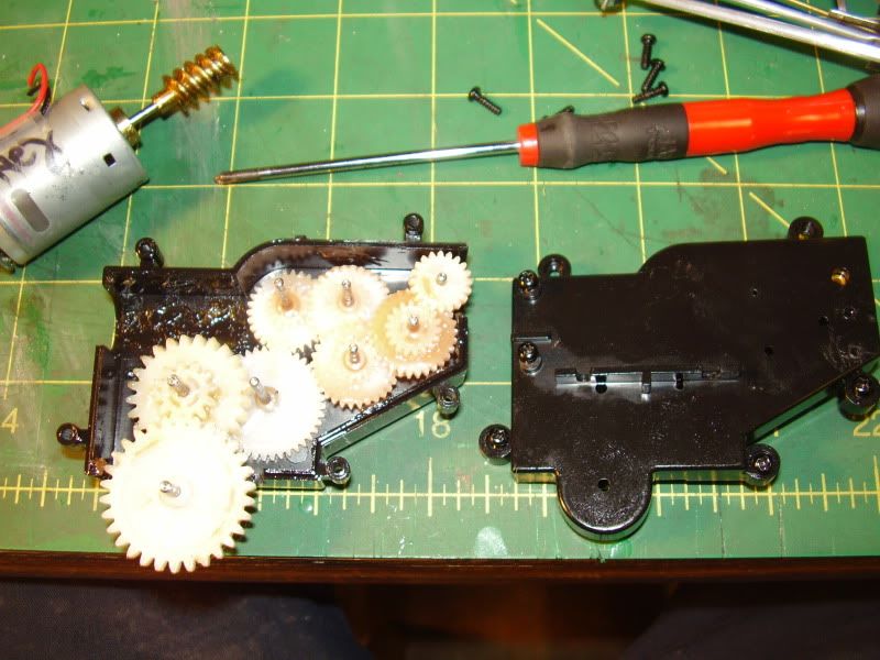
Kid-zilla wanted trains. Who am I to argue, but it has been squally, and I don’t have a good water proof power source. This gave us an excuse to tinker with and really observe Little Thomas. With only one motor forward and the stock axle back in place aft, he really sits “low by the stern.” If I put a bit of pressure on the stack, he’ll pull. Once my finger is off, he’ll do OK on a straightaway, but the powered forward drivers will seize or spin once he comes to a curve.
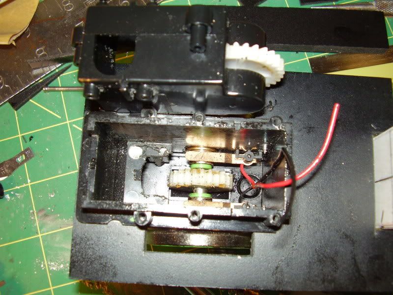
Based on this, I can see if there is a way to raise the rear axel. I think I will go with a bit of weight up front, first, as I fear more tinkering will only lead to new problems. I am really beginning to think the biggest issue with this project was not the intent or the motors but the low baseline from which I had to start. The requirement to jam those gear boxes into that small space seems to have posed a bigger issue in terms of alignment than I anticipated, and I bet if I hadn’t had to bend the “ears” for the mounting screws to make the gear box fit the space - or been a bit more precise in the process - Little Thomas would be out on the rails. Live and learn. The project must lurch forward!
Eric
Update:
Oldest Son and I did some tinkering. Contrary to my last post, the rear axel had to be held down. We cut some small styrene shims, placed them over the rear axel and let then perch there partially supported by the lower hull, then carefully set the upper hull in place. Little Thomas now sits on the level! We put him on the track, and he pulls a bit better. A passing squall wet the track, so I am not sure if his stall on the curve was the slipperiness, the lack of power, or the need for a touch of weight over the forward axel. We will wait for clear weather and dry rails before testing. I should mention I did place traction tires on him during an earlier round of puttering, so that direction is closed!
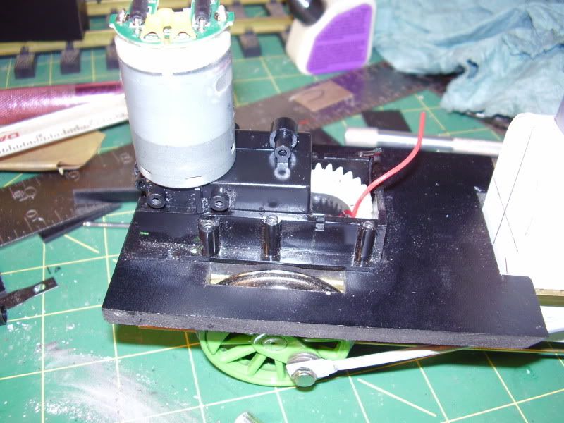
One observation I will add for those thinking of using one of these little motors. They run hot! One assisted loop around our little railroad leaves the lower chassis hot to the touch just under the motor mount. I think a better use might me something where the motor hangs external to the bottom of the loco / rail car / critter / whatever with a skirt to hide it. This would minimize the amount of shoehorning, helping to ensure a proper fit, and maximize the cooling. A bit more care in set-up probably wouldn’t have hurt in my case, either.
If this works, and Little Thomas can make the occasional loop around the track, I will letter him and call the project pau (finished) until I find a motor block or powered tender that allows for a more effective solution.
Updates to follow as progress…or lack thereof…merits.
Aloha,
Eric
Update:
Dry rails and sunny weather prevailed, and Little Thomas happily pushed a small low-sided gondola around our folded figure eight with minimal intervention. He did this for about 45 minutes, when the battery ran dry. This moral success merits proceeding to some dry transfer lettering, which I’ve never done before, and some light weathering, which is a long dormant skill.
Have a great week!
Eric
Update:
I lied…I let this sit on the shelf while I focused on DIY power supplies. This afternoon, before passing out in the Valley of the Nap where the Triple O’s dogbone pinches to accommodate an avocado tree, I had a fit of inspiration. I disassembled the motor block from my busted B’mann Big Hauler (The chassis went to the MIK 2019 ka’a wa’a; the loco had long since got a new chassis.) and, for the heck of it, jammed the motor into the lower hull of Little Thomas. It fit laterally and engaged the gear, but it did not fit vertically. Now I am wondering if I could cut the deck of the upper hull to accommodate and craft some sort of motor harness. On the one hand, that takes advantage of parts on hand; on the other hand, it could be yet another “almost” solution.
In the meantime, the heat shrink tubing I had used to make the wheels fit the axel of the Tamiya motor / gear block kit gave way. I’ll have to work for another “almost solution” to get back to where I was on this project, something that’ll creep along pulling a car.
The saga continues. Good thing I have those power supplies to build and a bridge to design!
Have a great week!
Eric
Are you having FUN yet? (https://largescalecentral.com/externals/tinymce/plugins/emoticons/img/smiley-wink.gif)


Modifying Percy’s gear box and eliminating unnecessary gearing for a vertical drive into another model. Perhaps this helps or maybe not.
@Joe: This would be down right infuriating if this was my only loco! As it is, it is just mostly frustrating. The poor old thing at least looks better than it has in years…
@ Rooster: Below please find a photo of my test-fit:
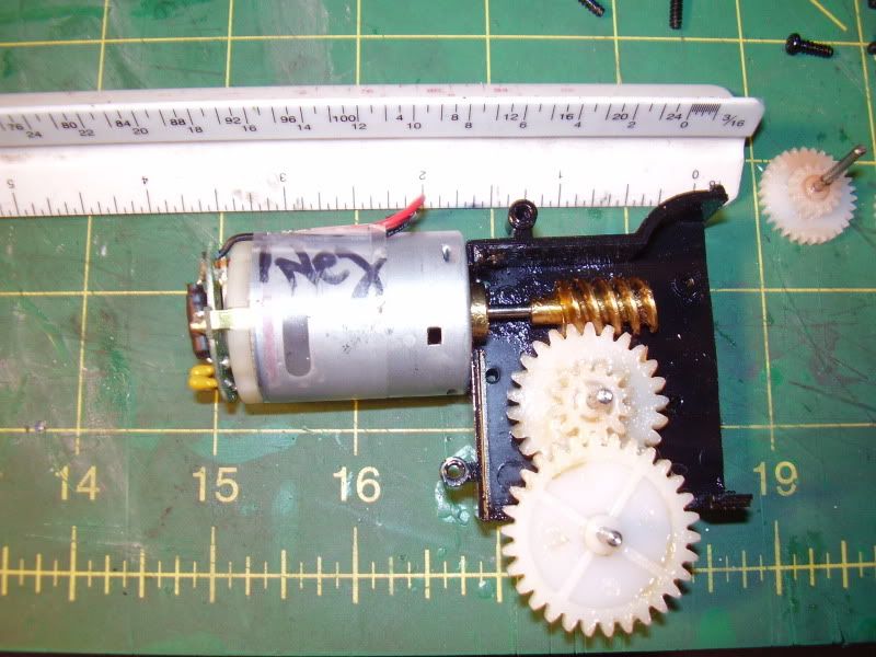
To the left is the surviving Tamiya motor and gear box. As mentioned, the axels are too small to take the wheels. To the right is the salvaged B’mann motor. You can see the worm gear engages the metal gear on the original axel almost perfectly. I ran some wires from a 9V battery to the motor. It’ll turn the wheels. I bought a 4.8V rechargeable battery for this project, which should be plenty if I wire it via the DPDT switch to the B’mann motor. Little Thomas is supposed to become bare bones plantation loco, so speed will not be of the essence!
I had considered mounting the motor vertically, but there is not space to go straight from motor to gear. I could look for R/C car or aircraft gears to make a gear box. If I go horizontally, I have to put some shims beneath the motor, then cut away the deck above it, and use the downward pressure of the worm gear on the drive gear to hold the axel in place vertically. The next issue would be holding it in place. It is a tight fit laterally, so arresting vertical movement should be the only issue. Either way, the Tamiya components would come out, the wheels would go back on the original axel, and then I’d have to design a way to keep the forward axel in place, as cutting out the innards to make way for the Tamiya gear box lets the axels travel almost 1/8" vertically.
I think I can make the cuts in the upper hull to accommodate without risking structural integrity. Horizontal would be simpler, but I’m not hard over. If getting this B’mann motor to fit fails, then I am going to seal up all the holes, weight Little Thomas down, and let him return to service under kid-power unitl I free the funds for a powered tender. Or I’ll chase another idea…
And now, only because it is cool, below find Wailua Agricultural Co. #6, a Baldwin / homebuilt hybrid. We saw her in new paint at a recent run to the Ewa Historical Railroad. She is one of three surviving O’ahu plantation locos, the last to feel steam rise in her boilers, and possibly destined for full restoration to powered operations:
Thanks again for the assist!
Eric
Update:
The forlorn hope project lurched forward a bit this weekend…For whatever reason, whenever I get Little Thomas off the shelf, the boys get pretty excited. As most of the tinkering lasts about 15 minutes before inspiration or failure, this continues to prove an interesting project.
We started by rubber-banding the abandoned B’mann can motor into place, then leveled it using some craft sticks left over from the Mik’s challenge:
The forward drivers spin freely on the axel which is still attached to the Tamiya gear box and motor, which, for the moment, is disconnected from the rest of the wiring.
The boys helped get the chassis and wiring harnesses out to the track at Haluku’ilio for the test. Below, they are using fishing weights recovered from a dive to balance it fore and aft:
We then wire the whole thing up. I finally got smart and used some spare wire and alligator clips to use for tests like this. Only took four years…
The tests were inconclusive. We had to fiddle with the rubber band to hold the can motor in place vertically. When we got that figured out, the lack of forward and after bracing meant the motor wormed its way off the gear.
After this, Kid-zilla went to bed, I finished my DIY controllers, and Oldest Son dozed under a tree. All stop…
As I see it, this project is now at four possible ways forward:
I also tried to use Little Thomas as a dummy this evening behind his track-powered “brother” Big Thomas. With the forward drivers rattling around a bit and the after axel sitting lower than the forward one, he just won’t track. Too bad. It looked pretty good and not unlike some of the doubleheaded plantation trains or those with helpers. After that failure, the track gremlins set in, and I chased derailments and power breaks, whihc was a change of pace from this project, anway.
Updates will follow as they are warranted.
Have a great week!
Eric
Boy, Trigg would be proud!!!
Update:
After walking away from this project, I think the logical way forward is to find a motor block and marry the shell to it. Nothing else solves the issue of rods / gear, and even the powered tender does not solve the issue of the have I have cut / ripped / ground the lower hull of this thing the point there is no guarantee it would work. As for the battery, charger, DPDT switch, etc., already bought for this project, I am going to use them on the kids’ LGB Christmas m2075, so neither the parts nor experience will go to waste.
To that end, I saw a “Stainz” chassis, sans motor, on e-Bay (Yes, Bill, I am finally going to risk e-Bay.) for ~$30. Given this is and LGB bit, I know motors and sundry parts will be available, so it seemed like a better bet than the PLAYMOBIL chassis and some of the other motor blocks I’ve been eyeing. I know this will be an imperfect fit, but it’ll also add to that “assembled from various parts” look that was a going in argument. Before I seek the funds release from CINCHOUSE, can anyone think of reason this would not work?
Thanks!
Eric
Naturally, I finally decide to try e-Bay, and the STAINZ chassis in question sold between coming home from work and finishing dinner…Sigh…at least I am resolved on a way forward…
Eric just sent you another link for a playmobil one, little more money but this on has the motor with it, Bill
" Rooster " said:
Note the ankle band which limits me. Already seeing good suggestions with this thread!
Takes me a while, but I just got it that Rooster was referring to the band on the chicken. For all this time, I thought he was speaking to the shoe straps on the kid.
But the really weird thing in this picture is the kid’s right hand being shaped like a moray eel, that’s creepy. Oops, can’t say that; his moray eel hand was “Special.”
Hmm, he’s wearing girl’s shoes, but I suppose that was the fashion then…
Other than that, what could possibly be remarkable in this photo?
Sorry, I sense that I’m drifting off topic…
Bill,
Thanks for the tip. I got your message that the STAINZ chassis was back on the market. It is now off the market…and bound for Hawai’i. I just replaced my Dremel, so figuring out how to marry it to the 2075 shell should give the VISA a chance to cool before I order a new motor.
And the saga continues…
Happy 4th of July!
Eric
Update:
Stainz chassis is on hand, which eliminates my issues with rods and gears and the like and gives me a solid base for this project. I should have begun with this, but live and learn…
This is a newer Marklin chassis, which is a lot cleaner in terms of screws and bits and fiddly things vis-à-vis the senior citizens on my shelf! On the other hand, all the rods are a soft plastic, almost a rubber, instead of metal. The inside was clean, and all the gears look good. Presumably a short-shaft Buehler will fit. There are no slots for external thrust bearings, so, unfortunately, I cannot repurpose Glitchy Gustav’s motor while I figure out how to best utilize “him.” There are 4x vertical brass posts I assume are for interior lighting and / or head and tail lamps. I’ll have to dicker a it to see what they do
I am placing the chassis next to Little Thomas on the shelf as I finish my bridge project. I have to give a good think as to how to marry this chassis to the shell, anyway. Today’s initial inspection revealed a number of possibilities, each with practical and aesthetic advantages and disadvantages. I’ll get some photos up later this week to better show my thoughts and to solicit ideas.
Thanks as ever for your patience with my running saga of trial and error!
Eric
OK,
This is now my primary project…again…Below please find the new starting point (left to right: body, upper hull, lower hull, Marklin chassis):
Obviously, the lower hull will not be part of the final product, at least in whole. My hope was that the upper hull would fit neatly over the new chassis…
…but that would’ve been too easy. On the other hand, I do think the deck should be salvaged to serve as a mount for the body, cutting fore and aft to let the deck settle flush against the chassis, tapping holes in it that align with the holes in the motor cover, and screwing it down. The Marklin chassis has four triangular tabs that jut upward; I am inclined to leave these and file notches in the deck instead to let them serve as guides.
The rather crummy “bow on” shot shows that this should line up rather nicely with some rather simple (I say that now!) styrene patches later:
The side view shows that similar patchwork is necessary:
A more perplexing question is what to do with that open space under the cab? I am weighing the following:
As ever, I appreciate your suggestions, and I thank you for your patience as I war my way through this project. I have to have a good “think” before committing saw to plastic. Having Little Thomas move, even for a while, under his own power for the first time since 1979 was pretty cool. No point in giving up now.
Aloha,
Eric
At a minimum I would be planning on steps and a rear pilot. A trailing truck would be nice, but are you ready for the engineering to add such a thing? If so, I would look at the smaller of the LGB or Bachmann wheels. The “normal” sized wheels would be too big.
David,
Got it. Bill had suggested something similar via e-mail.
One thing I am trying to determine is whether that space under the cab would’ve been “filled” with some part of the engineering plant or even a structural component on the real thing. That way, I could use the photo as a visual guide, and then mount rear pilot (learned a new term! Thanks!) and coupler to it. Back to the books…
Eric
Well…there is a prototype for (nearly) everything. So you could mount stuff under there. Air tanks, Power reverser, or maybe just extend the locomotive frame under there.