Large Scale Central

Carrick Furnace

Thaddeus Stevens was a U S Congressman from Pensylvania and a fanatical abolitionist. He built his reputation and fortune on iron. He owned and operated the Caledonia Iron Works from 1837 till the 1860s. His iron furnace was destroyed in 1863 by Confederate General Jubal Early at the time of the battle of Gettysburg.

Hope this gives you more insight into the early period of iron production.

Bob

When he’s done at Caledonia we can send him up RT233 a bit further to Pine Grove Furnace which had rail road service as well. :grinning_face_with_smiling_eyes:

How am I supposed to get any modeling done if you keep giving me research.

New class of Devoning … :thinking:

This is for Jim, no one else is allowed to look.

So here is the 3D model pieces to date and some insight into the various parts, how I approach it, and how I see it assembled in my mind.

Starts with the brick base and then the cast iron base

Brick BaseIron Base

Next I add the cylinder assembly and then the posts.
CylinderPosts
Then the guide rod assembly. The tub. Then the tub lid.
Guide Rod

Tub Lid

Then the exhaust and intake pipes and a piece of brass rod for the flywheel shaft.


Then the fly wheels.
Flywheels

Even as I was throwing this together quickly I realized a problem and had to make some on the fly adjustments. This is why assembling these things virtually works for me. I had the pins for both the guide rod and the pins for the flywheel as part of their respective assemblies. But that would prevent me from adding the drive rods. So I had to slice off the pins and create sockets for them in the guide and the fly wheels and lengthen the pin to match the hole I know made. Now I will be able to put the pins through the drive rods and then attach them to the flywheels and guide rod.

1 Like

Thanks, Devon. Helps me grok the thinking process. Or is that “think the grokking process”???

That is a good point! I forgot about Pine Grove Furnace.

So hear again is one of the reasons I have come to appreciate virtual modeling and virtual assembly. Not only do you have to tackle real world problems it can actually teach you something that was not intuitive to you from the start.

One of the things, if you have been following this thread, that has bugged me is the “flywheel crank shaft”. I can’t see it. Well now I am thinking there is none at all. I can’t see how there can be a single shaft to which both drivers are attached and here is why. Maybe someone can offer some insight.
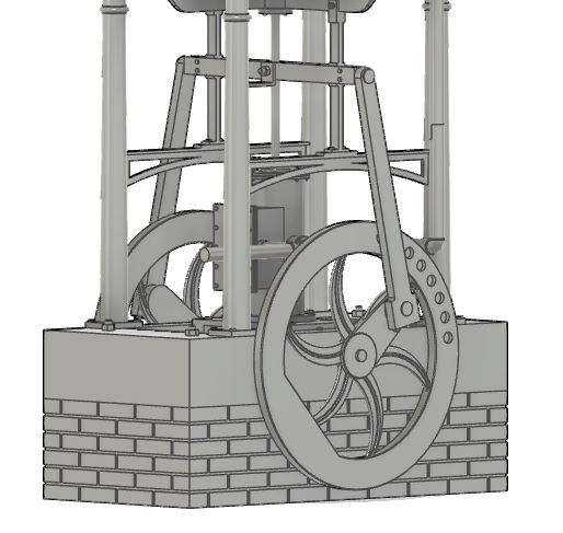
Flywheel problem

So I went to design the drive rods to connect the guide rod (my name for it) that is being driven up and down by the steam cylinder to the flywheels. First minor problem was that I did not have the wheels properly quartered they were off by 7.5 degrees. I discovered this by first making one side and then making a mirrored part in two planes (left and right/ front and back). This produces a part that is exactly quartered to its counterpart. When I looked at the opposite side of the model the holes didn’t line up. Easy fix you just rotate the driver on its center line axis until they do. in this case I needed to rotate it 7.5 degrees.

Now with that all done and me being very proud of myself, a giant glaring problem arose. It wouldn’t work!!! If you look at the above picture when the guide rod thing goes up it will be pulling the flywheel pins up. When it goes down it would drive the flywheel pins down. If you haven’t figured this out yet it will be trying to drive the fly wheels in opposite directions which would make for some serious ugly if they were rigidly attached to the same shaft.

On a steam locomotive we drive opposite drivers which are attached to the same shaft with separate cylinders and separate drive rods. They are independent of one another. So they themselves are quartered (for the lack of a better term) from one another. So they can drive their respective driver in the same direction while installed on the same axle.

This can’t happen here. So What I am thinking unless someone can point me to the folly in my thinking is that there is NO single central shaft connecting the flywheels. They have their own shafts attached to their own bearings and everything works independently and if I am not mistaken, this means when this thing is humming along the flywheels are doing so in opposite directions.

If this is the case and they are independent it brings up another observation. Do the flywheels even need to be quartered or would it be indifferent? Or would it even be say better for them to be 180 out instead of 90 degrees out? Should they be 0 degrees out?

This is your fault Rooster. And this is why my other projects get Devoned.

Now with the post you guys are posting I think I am at least partially getting the drift of what is going on with these more or less primitive furnaces. If I understand this the big stone furnace next to my blower it way more complicated than a pile of rocks. Inside this thing was the melting pot ( I don’t know what else to call it). Ore was dumped in the top it and a fire built below it. The fire was fanned with my blower or bellows. Once it was melted the ore was let out the bottom I am assuming??? Since slag floats I further assume the good molten iron was drawn off first and then when they thing emptied to the point it reached the slag then the good iron was removed and the slag drawn off to be dumped somewhere.

Is this basically right? But now it begs to see how the molton iron and slag were transported or otherwise used from these furnaces. Was a prepared mold brought to the furnace and the molten metal poured directly into the mold straight from the furnace. And then only the slag would be hauled away. That would make the most sense to me. Why move the molten Iron when you can move the molds a lot easier.

Bob,
We probably shouldn’t mention Cornwall Furnace in Lebanon as it might send Devon over the edge!

I was going to mention it … :kissing:

Here the deal. You can mention anything and everything you want. But then you had better start figuring out some of my problems and questions. I need answers and solutions not more things to give me more questions and problems.

:laughing:

So I think I am done with the blower. I am sitting here looking at it and now that I have separated the flywheels onto their own shafts, I think I am done. If there are parts missing I don’t know what they would be. So this is ready for a test print.

Next up is the boiler set up. To connect the boiler to the blower I plan to make a bunch of generic fittings and pipe that I can use much as it would be done in the real world and once I place the blower, boiler, and furnace I can use those fitting to plumb it.

Yes, at Hopewell Furnace they casted the molds right by the furnace.

hopewell-furnace-national

In this picture you can see the two large cranes used to move the items in to range.

1 Like

https://www.cornwallironfurnace.org/tour/furnacetour1.htm

Oh no. Now I need cranes.

Thats a neat place. I would enjoy myself there. That last video really answered most all of my basic question on early iron production.

Some simple observations. As stated the furnace was the center. Ore was dumped in and iron came out. What was interesting is that the molds were filled right at the furnace, but also the floor was used to make troughs that the “excess” iron could be poured into to make ingots. These ingots could then be used by blacksmiths and hammered and pounded into other products. So the furnace acted as not only an end product facility where finished cast goods were made but at the very same time refined iron metal was also produced for further processing down the line.

Not only blacksmithing but I am sure smaller foundries across the country would buy the pig iron ingots and remelt them and cast them.

At any rate I think I have enough of the process figured out to satisfy my curiosity. And more over give me a small industry to model. I have an unused corner of my layout that will now have a small blast furnace producing pig iron. . .

Who knew that not only was gold and silver found in Burke, Idaho but a large deposit of iron ore was also discovered.

Not to mention the National Museum of Industrial History

Stop it.

Now I am a water guy, 26 years and counting. A large part of my job is pumping water up the hill to the reservoir to gravity feed down to the city. This is an industry you might say I know a little something about. It never occurred to me to model my profession. For one electric line shaft turbine motors are BORING :sleeping: :sleeping: :sleeping: :sleeping:

image

Another is it just simply never crossed my mind. Where I used to work and got my start in this biz might have something I would be far more interested in modeling maybe and that was an old surface water plant that was long since out of service but still operational. It consisted of two electric pumps that I believe were large centrifugal pumps. The pumping station actually sat in a concrete building below water level so that the pumps were always primed. That could be a fun model.

But that large steam driven water pump could be really really fun. And I just so happen to have a spot on my layout that is a depressed section that sits where ground level used to be and now is 18 inches lower than the train layout. It would make a perfect “lake” where a pumping station could be placed.

Thanks Bob