I’d like to scratch build some freight cars, but I’m not clear on how the underframe is put together. Specifically, how do the bolsters and other cross-pieces intersect the longitudinal pieces? Do the long timbers sit on top of the bolsters? Or are they notched to fit together, “lincoln log” style?
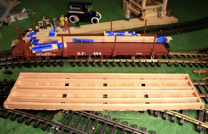
Ray - I’m assuming your referring to wood cars which all share a similar frame structure. I’ll borrow some pics from my flastcar tread to try and answer your questions. The basic frame is composed of two side sills and two end sills. In this photo an assembled outside frame sits on top of the plastic flat with some pre-cut lumber inside it… [url=lsc.cvsry.com/EBTTank/Wood_Flat_1_1200.JPG]
(http://lsc.cvsry.com/EBTTank/Wood_Flat_1_720.JPG)
[/url] [url=lsc.cvsry.com/EBTTank/Wood_Flat_2_1200.JPG]
(http://lsc.cvsry.com/EBTTank/Wood_Flat_2_720.JPG)
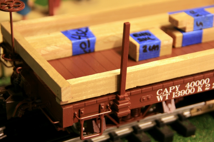
[/url] Note in the close up that the side sills are cut to support the end sill which is dimensionally smaller in height. The next major component is the center sills. There are usually 4 of these. The two in the center are space close together and handle the stress of the couplers. The other two are more widely spaced to add stiffness to the overall frame. The center sills are the same height as the end beams. [url=lsc.cvsry.com/EBTTank/Wood_Flat_5_1200.JPG]
(http://lsc.cvsry.com/EBTTank/Wood_Flat_5_700.JPG)
[/url] [url=lsc.cvsry.com/EBTTank/Wood_Flat_6_1200.JPG]
(http://lsc.cvsry.com/EBTTank/Wood_Flat_6_700.JPG)
[/url] Note that the model construction technique for the flat I built adds the deck before the center sills to make gluing easier. It’s likely that the railroads built the entire frame first before adding the deck. The final components are bolsters and needle beams. My model uses a very simplified bolster which is just a piece of wood glued and nailed to the center sills between the side sills. It is just slightly thicker than the height difference between the center and side sills. They lay across the center sills. The orientation of the needle beams is difficult to determine from the photo unless you realize that they do not intersect the sills at all. The needle beams are notched on the ends to drop inside the side sills while still attaching to them. They lay across the center sills the same as the bolsters. [url=lsc.cvsry.com/EBTTank/Wood_Flat_8_1200.JPG]
(http://lsc.cvsry.com//EBTTank/Wood_Flat_8_720.JPG)
[/url] [url=lsc.cvsry.com/EBTTank/Wood_Flat_16_1200.JPG]
(http://lsc.cvsry.com//EBTTank/Wood_Flat_16_720.JPG)
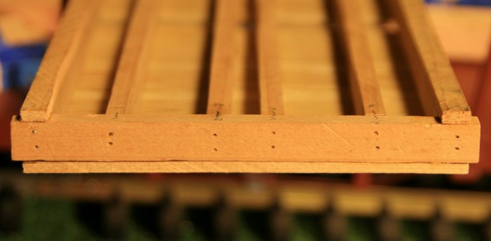
[/url] In the above photo don’t confuse the lack of focus and the shadow of the needle beams as intersecting the center sills. They do not. Look closely at the top side and center sill - once you focus on the orientation, the optical illusion of the intersection goes away (I hope). The function of the needle beams is to distribute upward tension from the truss rods. through the queesnposts to keep the center of the car from sagging. BTW - I really didn’t know much of this three weeks ago when I started on this flat. A lot of time was spent experimenting with drawings to figure out the relationships of the parts on the 2D plan.
Ah, now I see! The last two pics in particular were very helpful. Thanks, Jon!
You’re welcome Ray. Email me if you would like the basic wood flat car plan that I started from.
GR car plans follow that pretty closely.