Large Scale Central

C.V.S.Ry. Shops to restore Jackson & Burke #4

The last step in preparing J&B #4 for road trials was a bit of paint. Most of the boiler and tender just needed cleaning and touch-up, but the cab roof was in need of refreshing. I masked with delicate surface tape and a plastic bag…

Then shot two coats of Rustoleum Rusty Metal Primer…

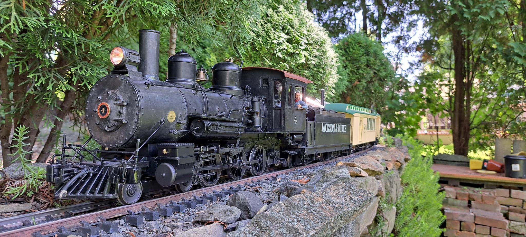
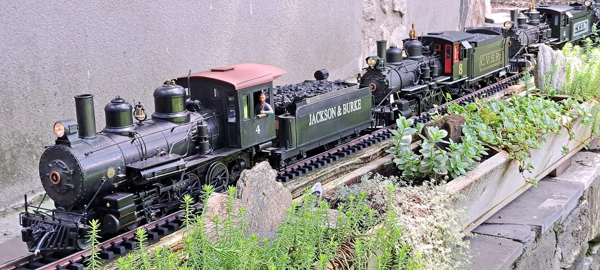
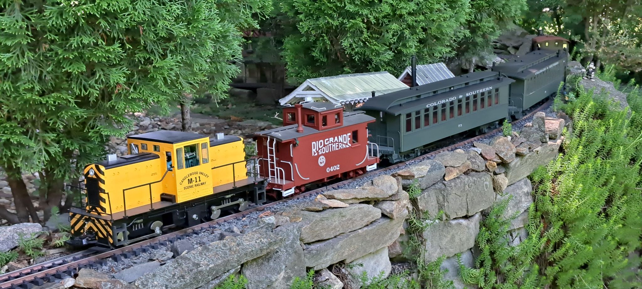
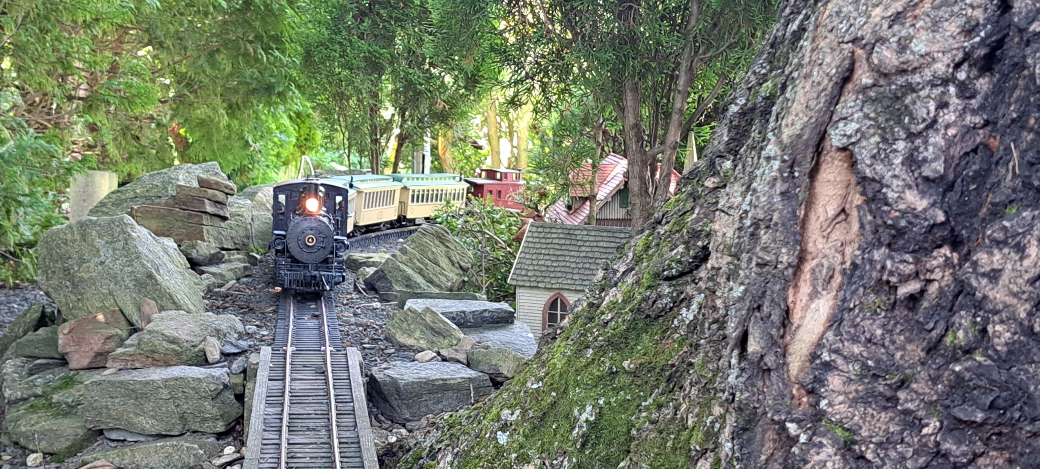
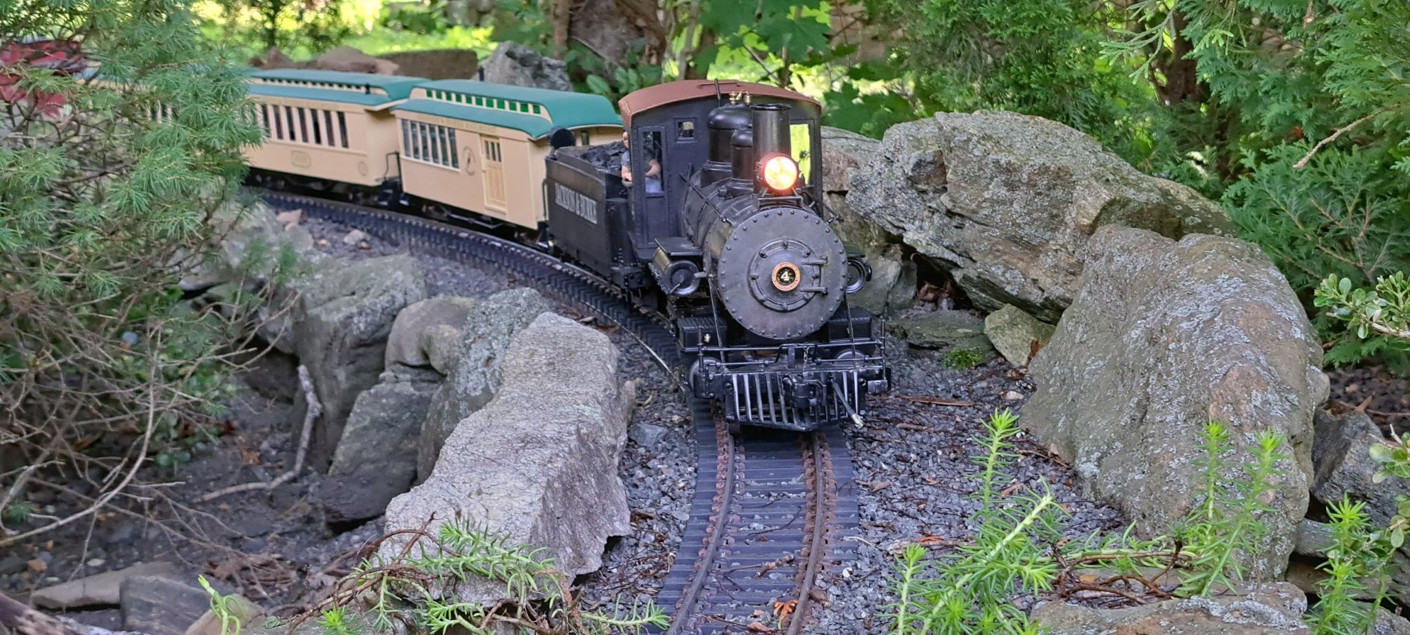
When that was dry, #4 returned to the rails, was mated with her tender and proceeded to run road trials on the outdoor. First up; a passenger consist with a caboose…

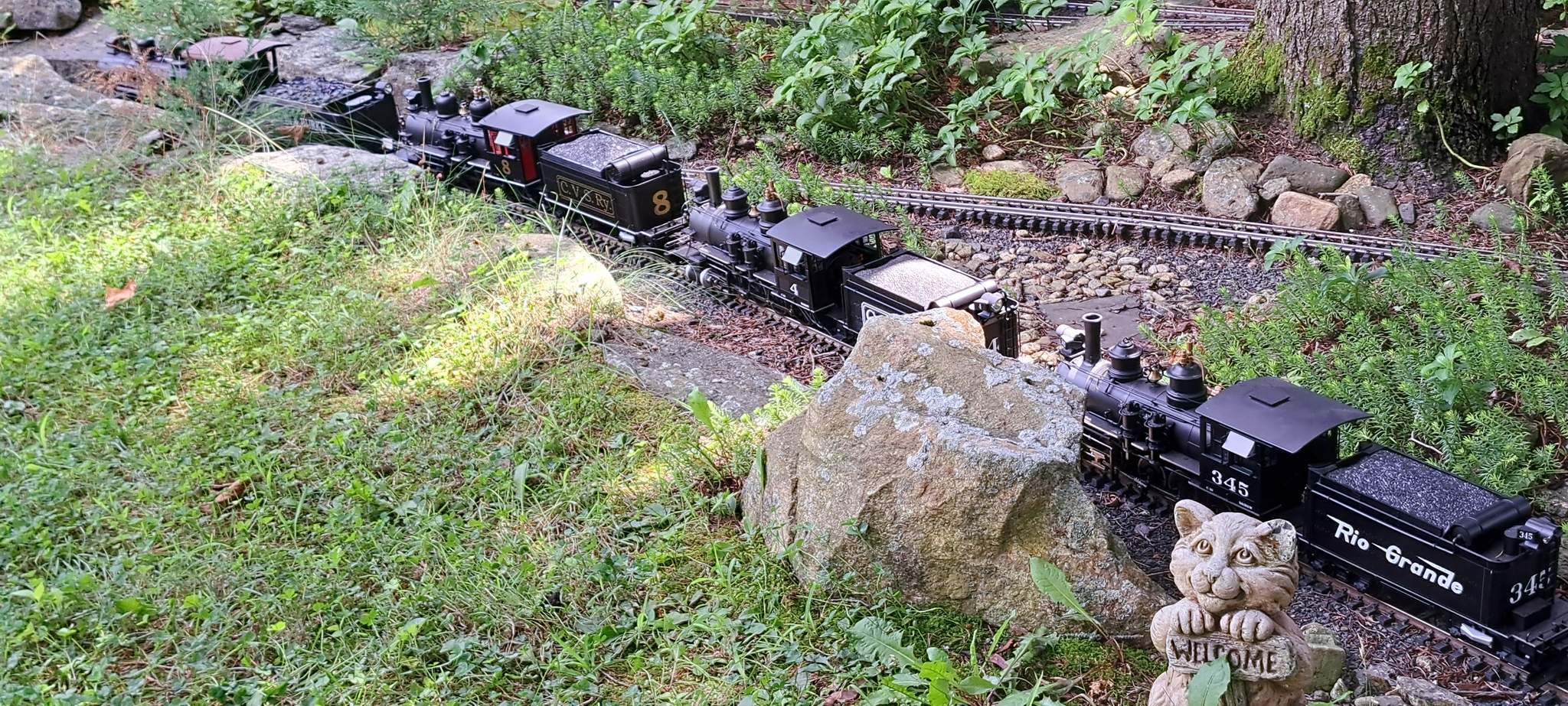
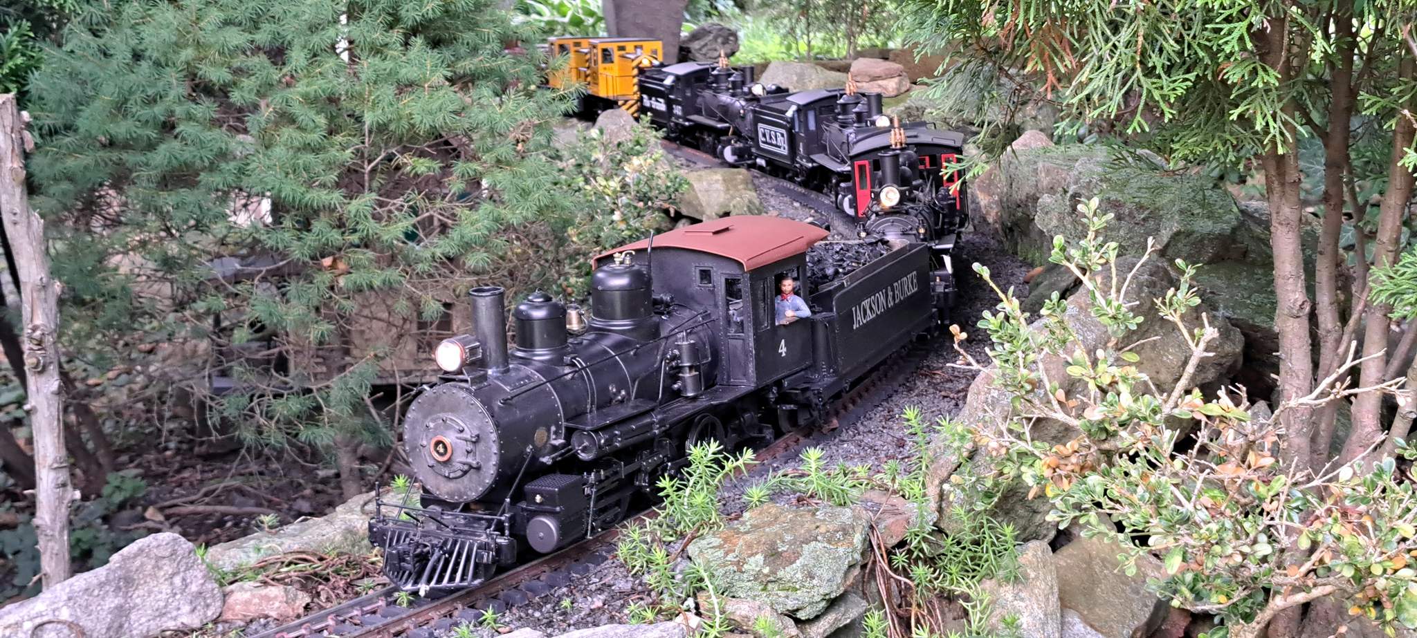
Unfortunately, the 4% was just too much and she started to slip even before the curve. M-11 was called out to assist up the hill…

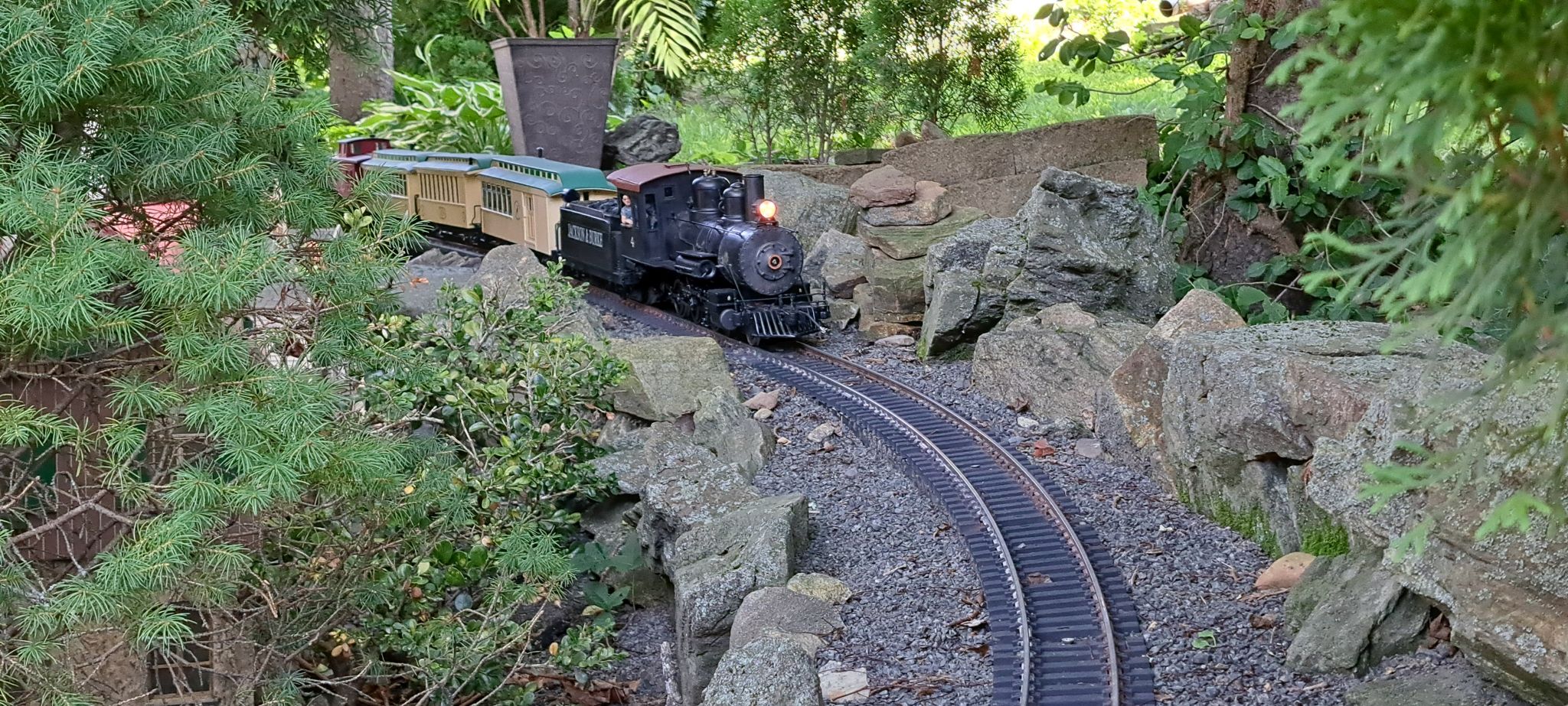
#4 was able to handle the braking duty down grade without assistance…

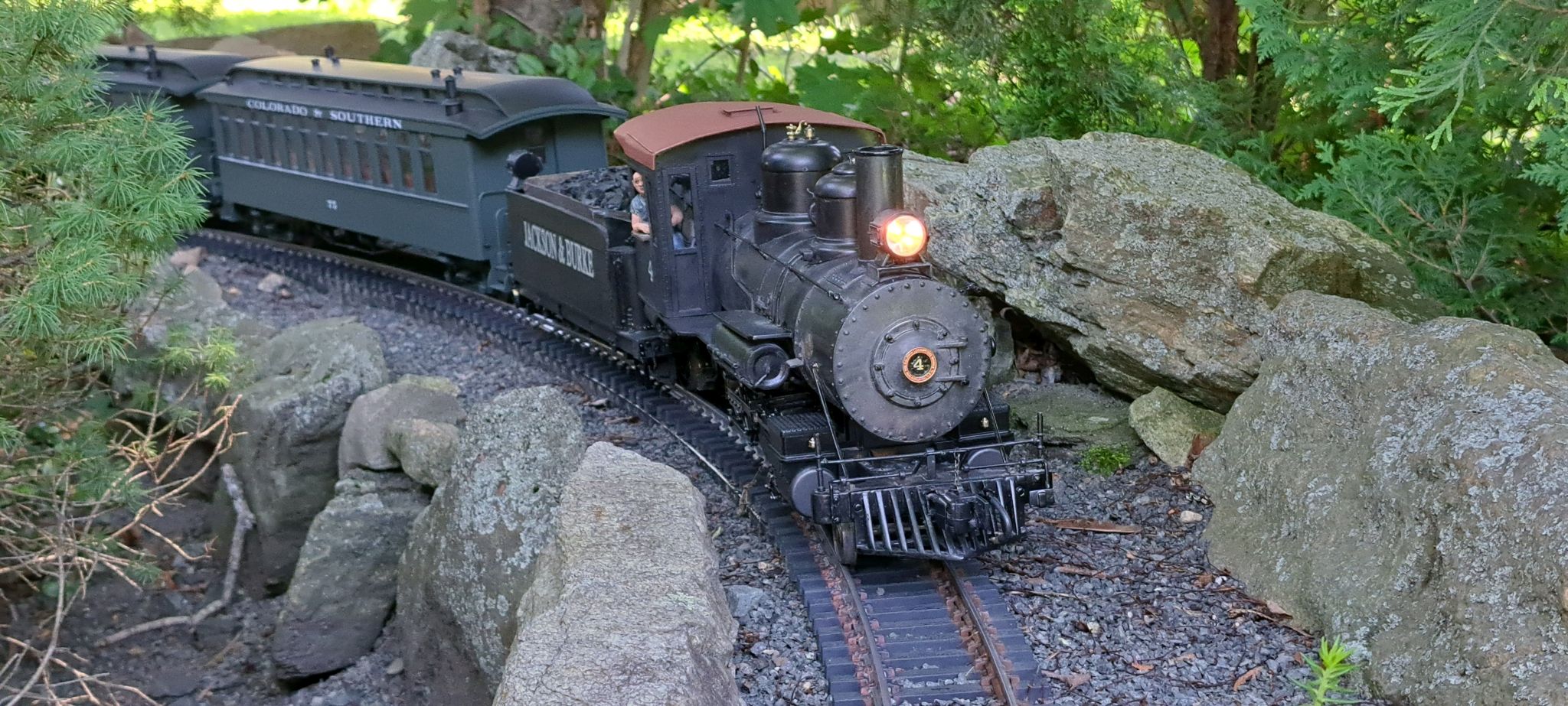
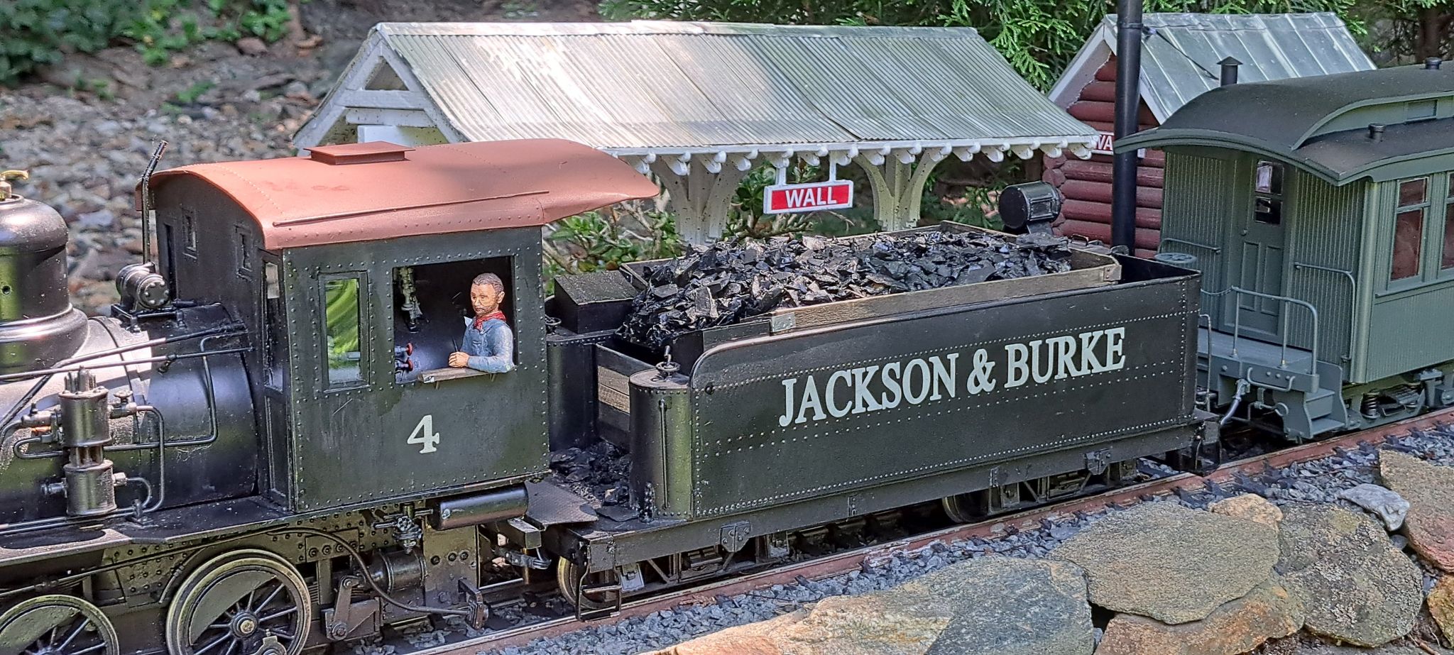
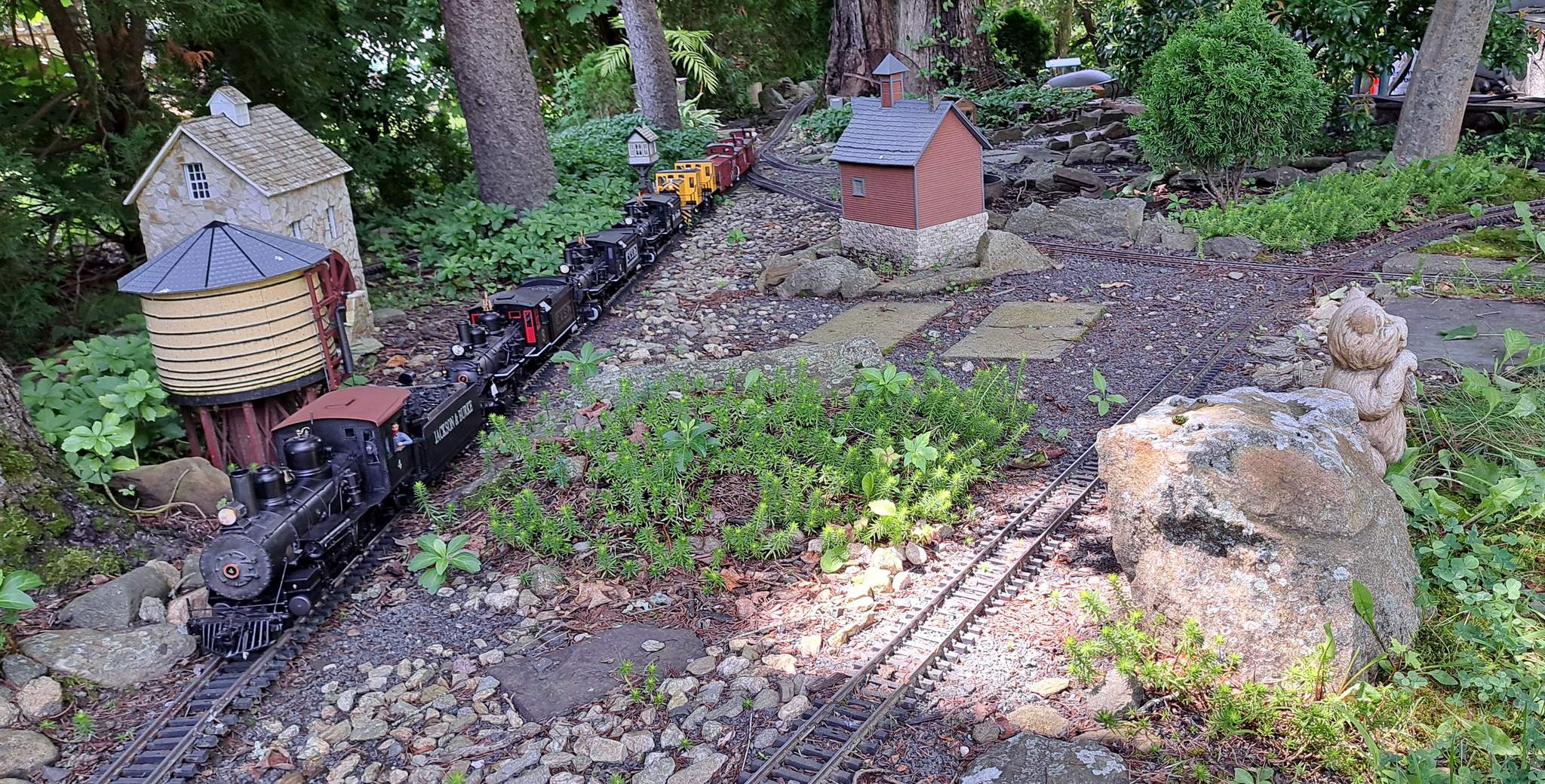
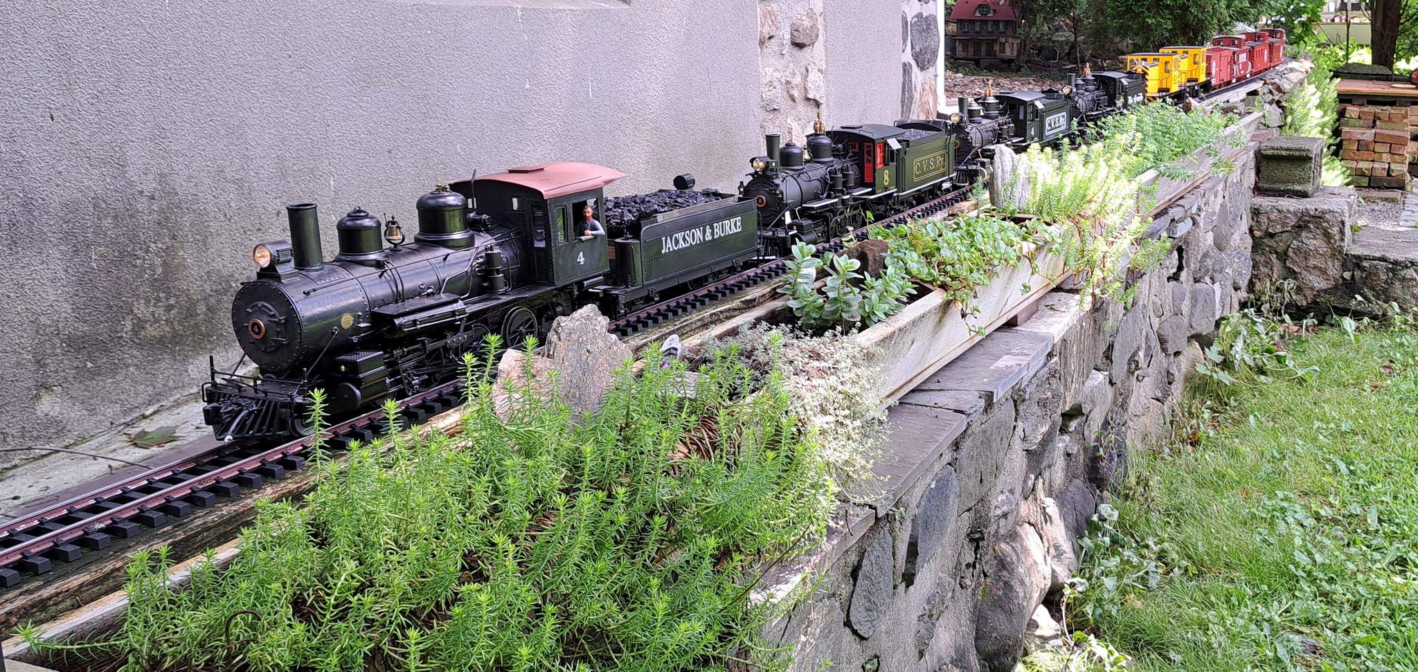
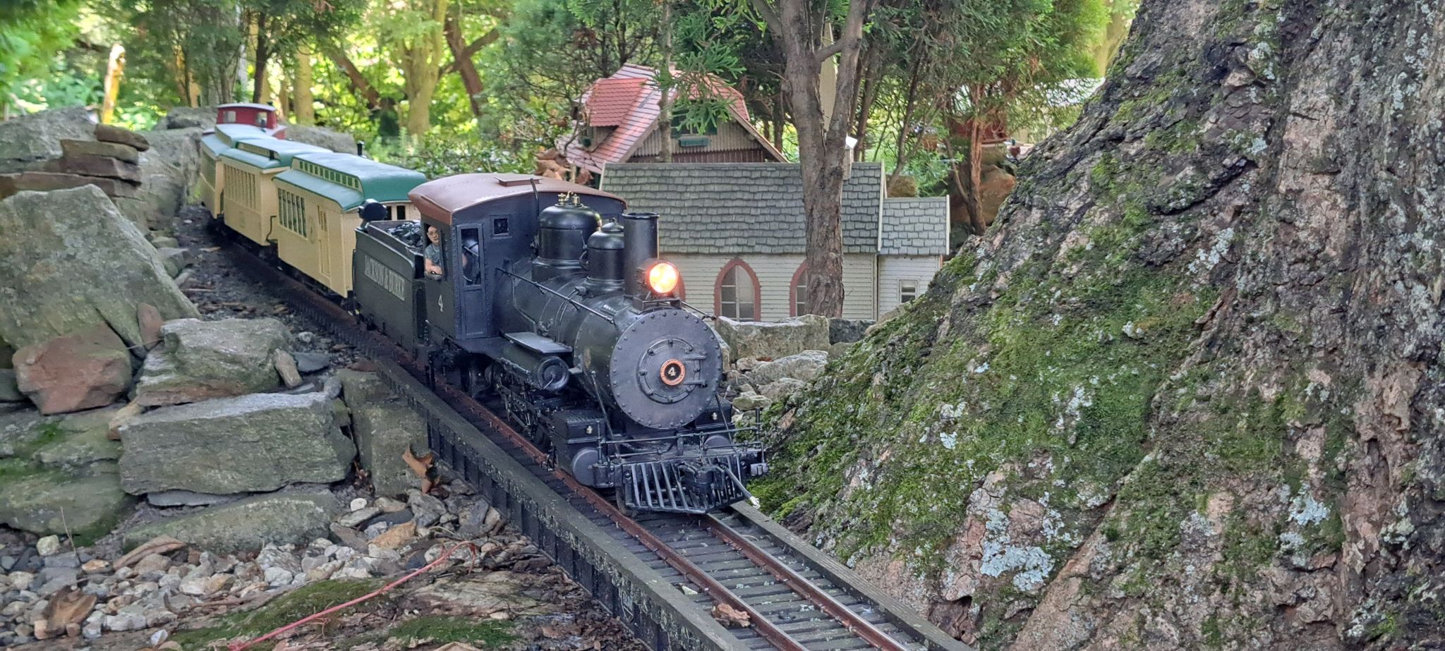
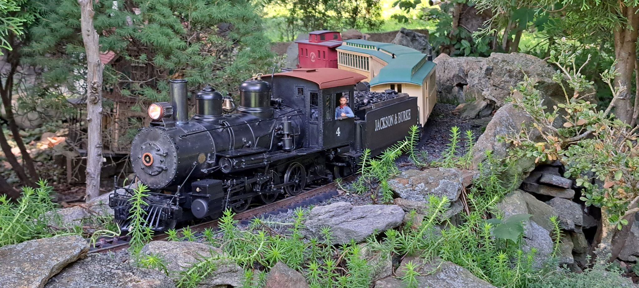
Then it was time for a very special run. An all Jackson & Burke passenger consist…

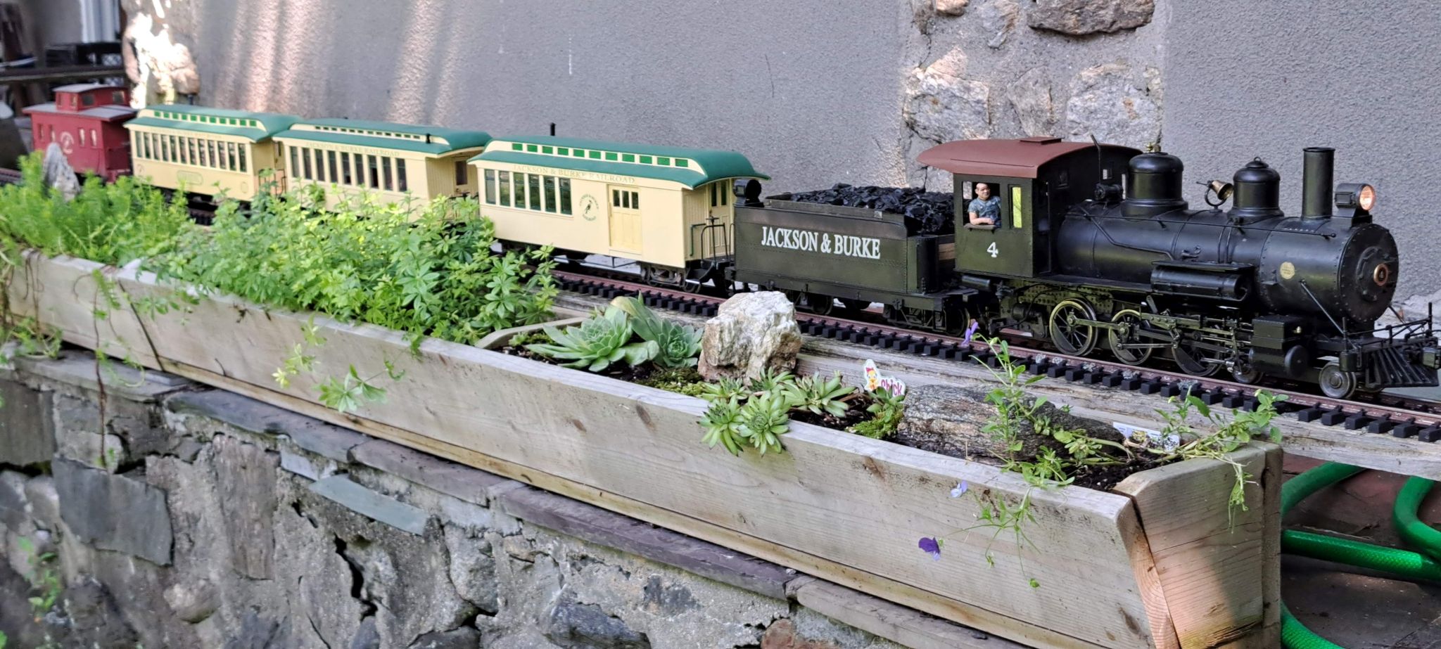
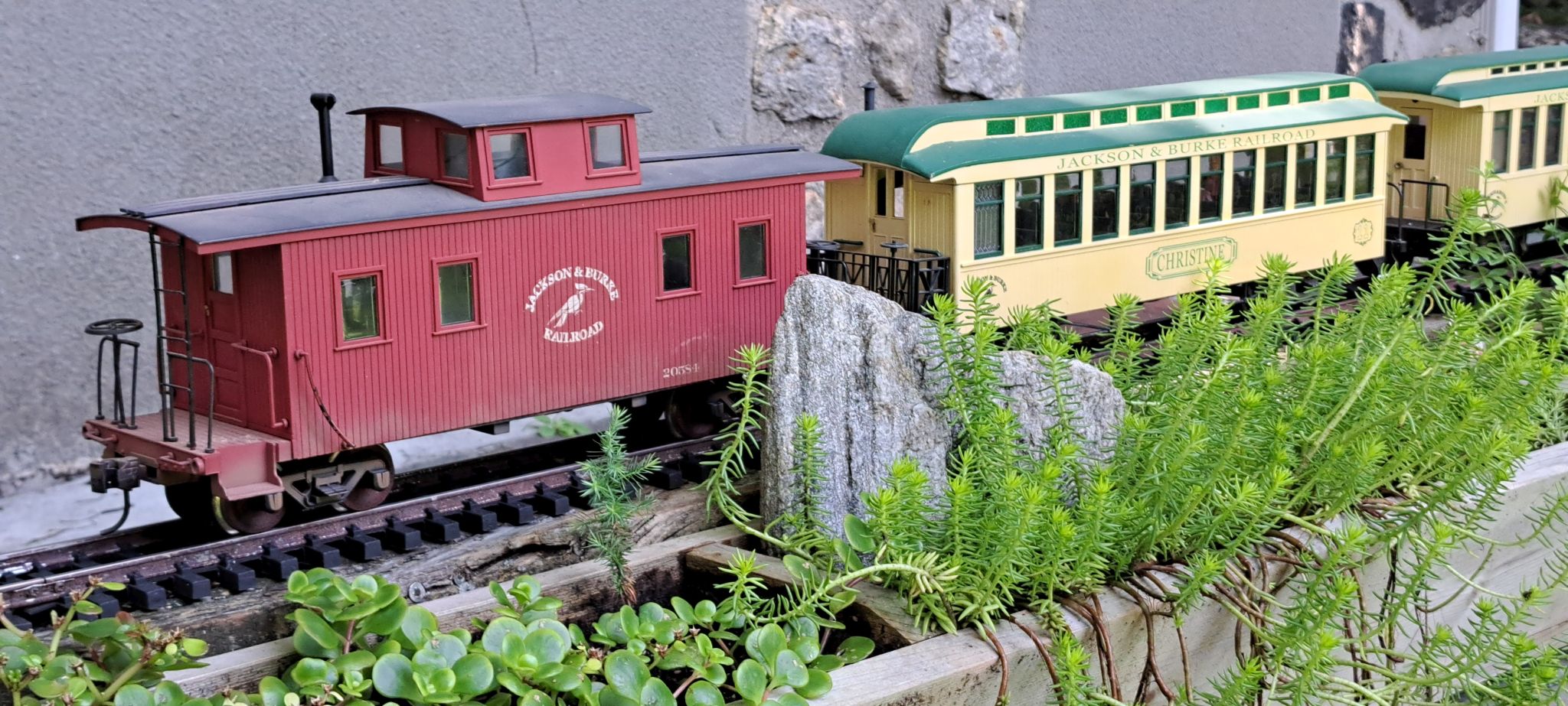
The caboose arrived first after a long circular route from Burke, VA to Connecticut via Ottawa Canada and Northern New England…

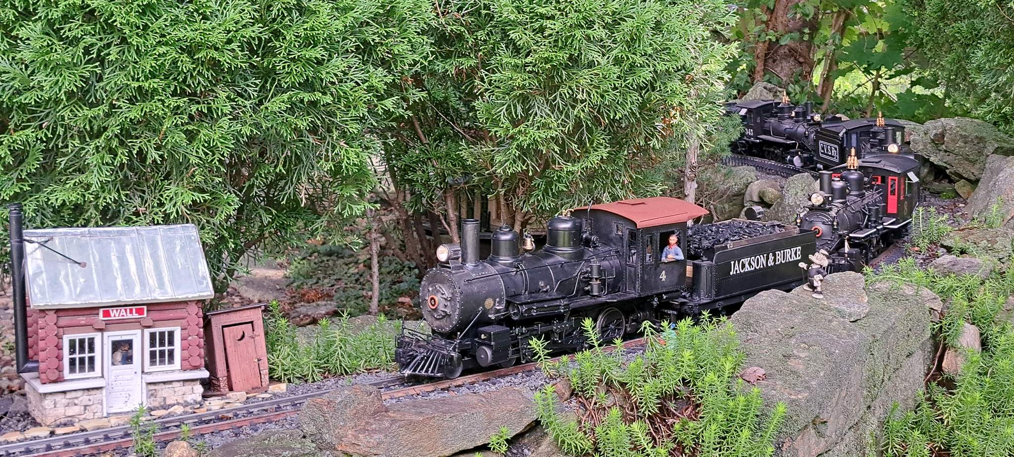
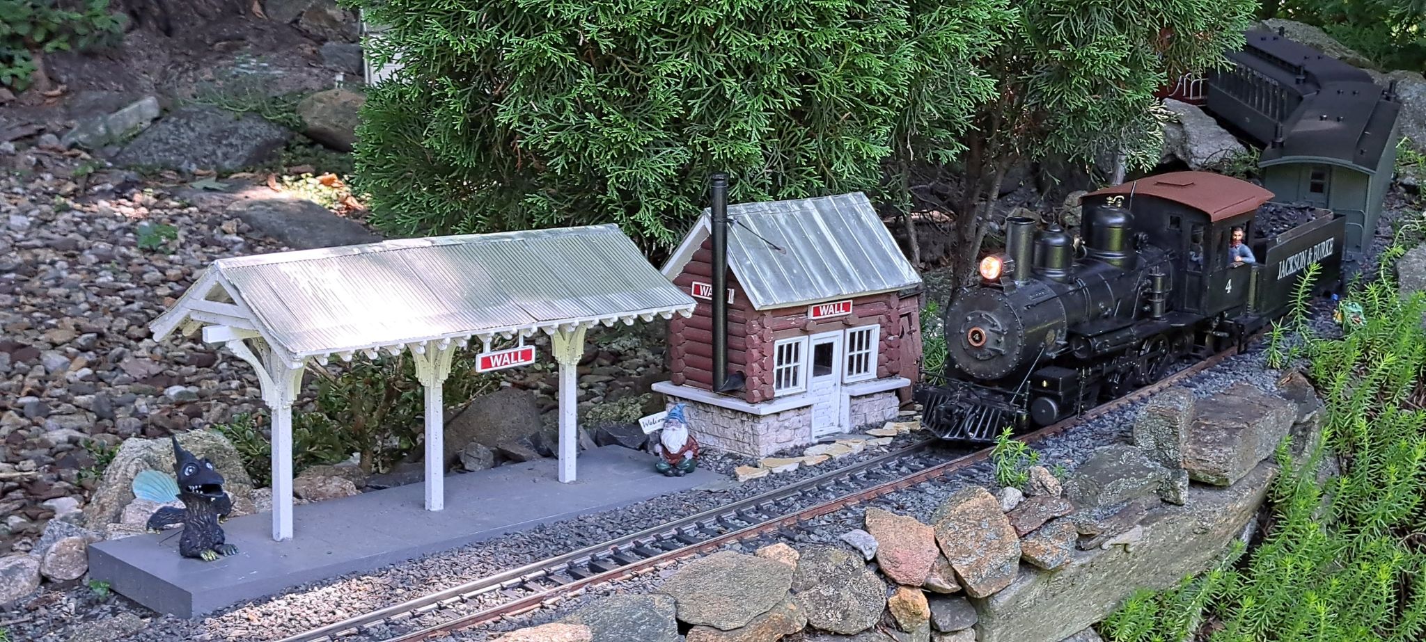
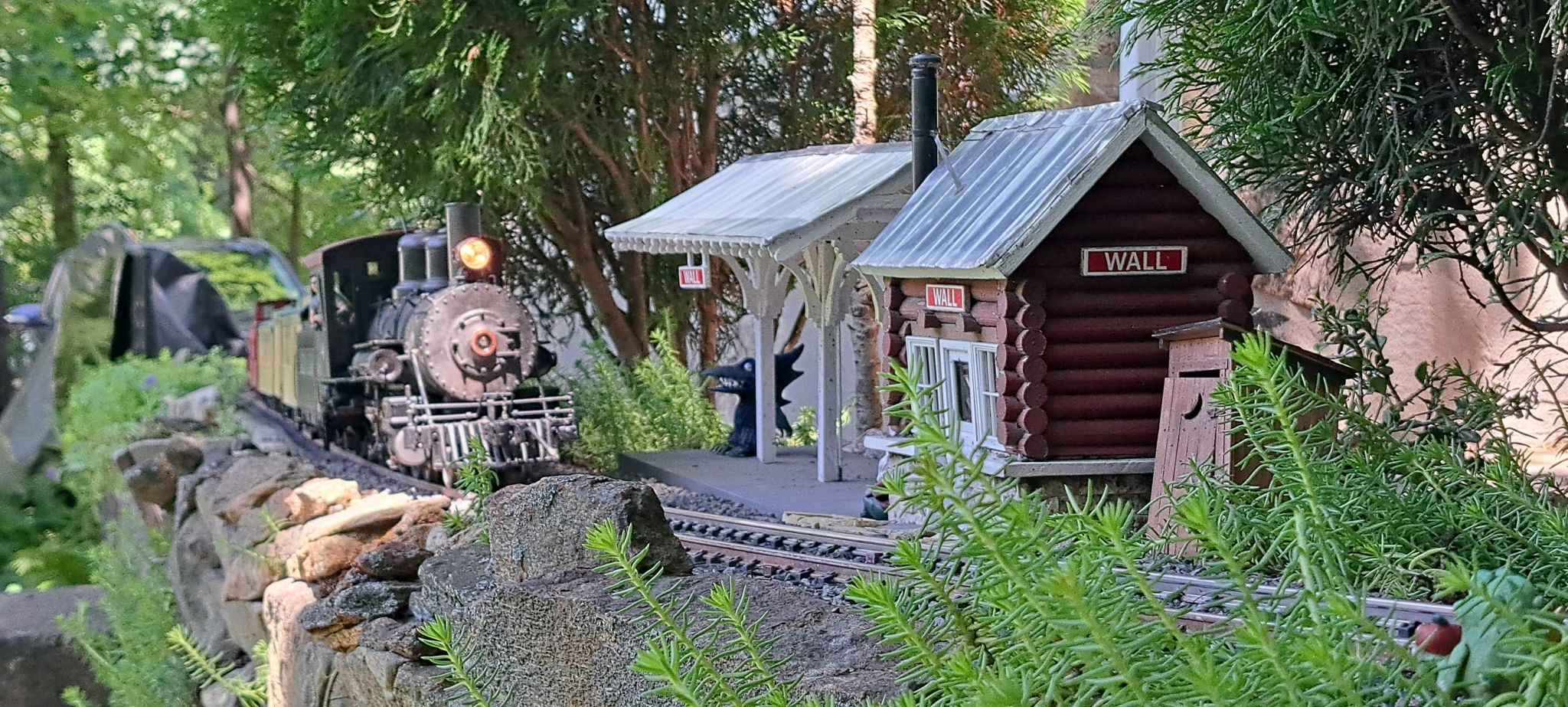
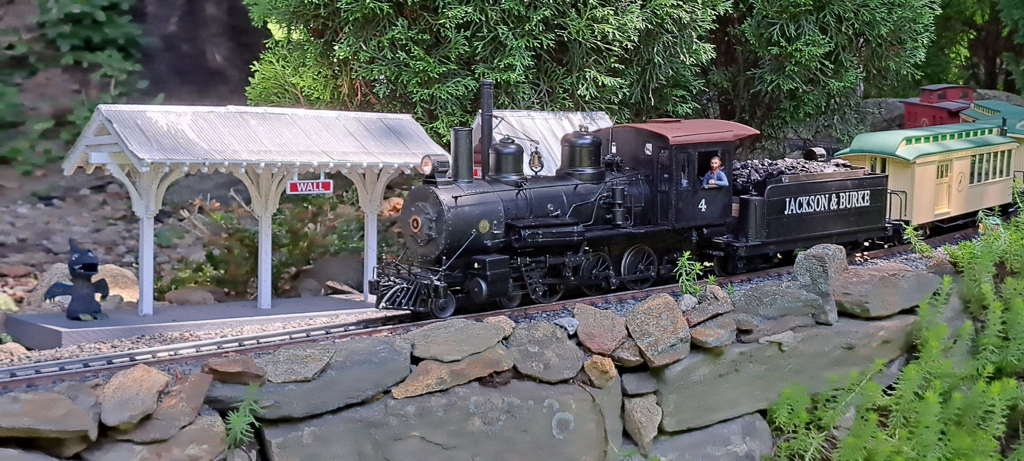
The passenger consist first went to Ken Brunt and later to me via his estate sale. Seen here approaching Wall Station up-grade. This consist is significantly lighter and #4 handled it with ease…

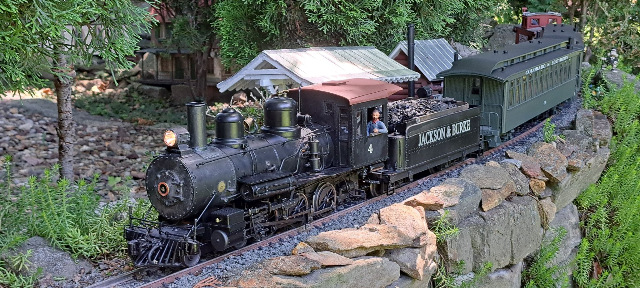
This scene would not be possible without the modeling talents of Bruce Chandler and Ken Brunt…

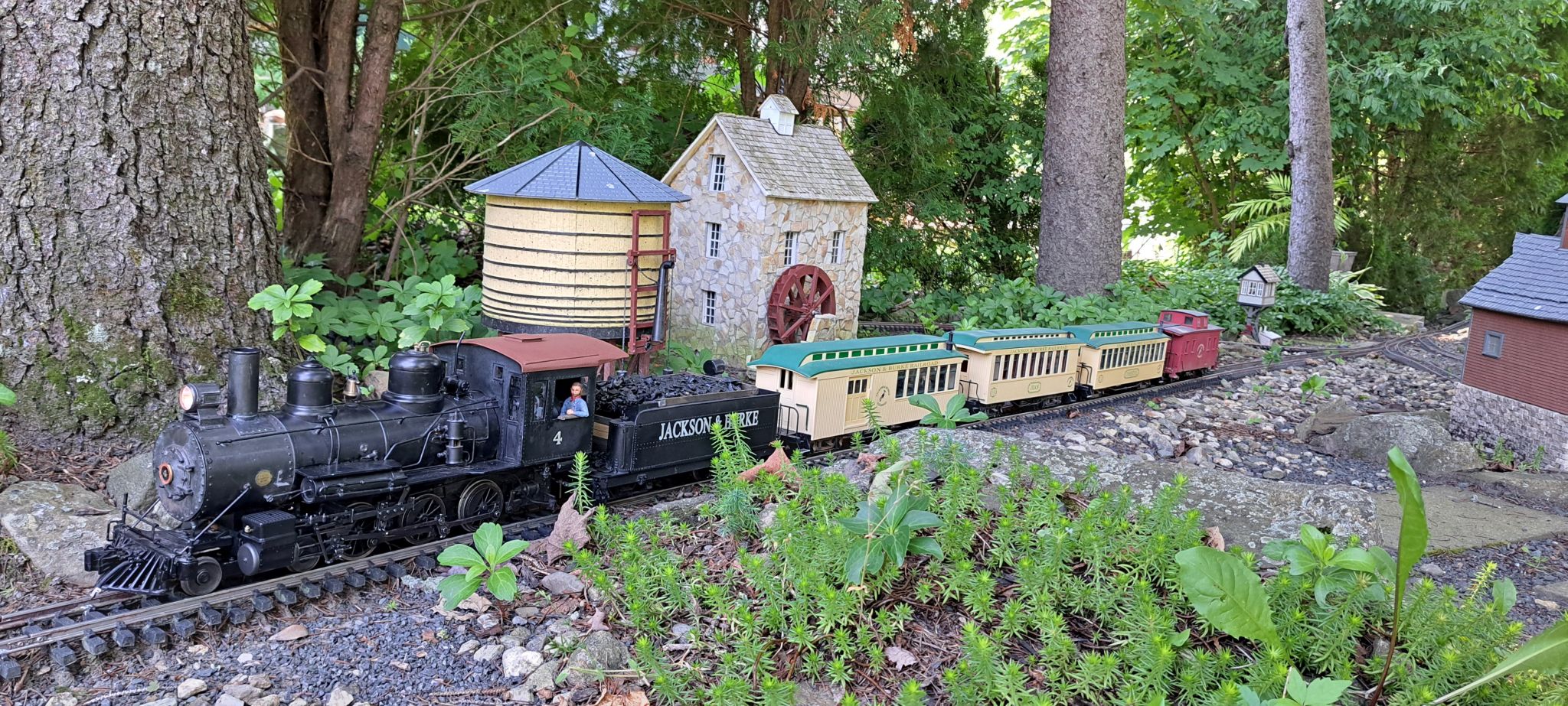
I want to express my thanks to Bruce for this engine. It has wonderful details. fantastic character and runs quite well…

8 Likes

:heart:

Just because I can…

J&B #4 lead a Quadruple Header / MU train of all operable road locomotives at the Candlewood Valley Scenic. Seen here at Pine Tank, the train is about to split in two allowing it to traverse the wye…

The diesels and cabeese were cut off while the steam locos ran through the wye…

The diesels and cabeese re-joined the consist on the west leg for the trip home. Seen here rounding Coal Dump Curve…

And approaching Wall Station…

And finally, passing the Ken Brunt Memorial Planter…

All of a sudden I get the feeling I have too many locomotives!

2 Likes

Give it time, the feeling will pass.

Great shot !!

Don’t think I have ever seen an overall distance shot from that angle!

J&B #4 has served well for several months and quite a few runs around the railroad. Recently, the front truck began derailing way too often. I took it apart and tried several things to try and keep it on the track like adding weight and even a spring. None of that worked. Upon close inspection, Bruce’s home brew truck was just worn out. The axles pass through a frame made from aluminum angle with no bushings. The holes have worn oversize causing the truck to no longer sit square on the rail.

I could try and copy Bruce’s design and make a new frame - OR- I could be lazy and buy a Bachmann Annie truck and adapt it to Bruce’s mount. Before I go that route, could anyone with an Annie please measure the wheelbase and the wheel diameter for me?

If I do try and fabricate my own copy I’ll need to figure out how the wheels are attached to the axles. Nothing obvious, but there must be a insulating bushing as they don’t short. I wonder if Bruce remembers, Nah - not likely!

1 Like

Jon, this is a different style, so probably isn’t helpful… So fwiw, the wheels are 3.43" c to c, with .96" dia hubs and 1.19" dia flanges.

Thanks. If it’s an Annie., the measurements are probably good. The one pictured is from the latest version and very similar to how Bruce built his.

The biggest appearance difference to what Bruce fabricated is the wheel flange. Bruce’s truck has fine scale flanges. Another reason why it doesn’t want to stay on my track.

Heh…I don’t even remember doing anything with this…but it might be the scale flanges that are messing you up? Can you try the existing setup with large flanges? :innocent:

Maybe, if I had some small diameter wheels. Wait, didn’t I buy a set of the small; Bachmann wheels 15 or so yeas ago. I haven’t seen them in a while. Will look.

Unless new wheels have a slightly larger axle diameter they probably won’t help because the enlarged holes in the truck frame are what is causing it to be out of square.

When I first started running it, I had very few problems. It just didn’t have a lot of miles left in it!

I think you’d do better to install proper suspension. That’s a long wheelbase, so you need to allow the wheels to ride over bumps or track mis-alignments.

With the 4-6-0 front truck, I remove the 2 nylon plugs shown in Cliff’s pic (one with the arrow.) The wheels are held by the metals strips, but now the whole thing is floppy and stays on the track. Just remember to put some insulation down the center between the 2 metal sides.

The traditional British way to provide similar 3-point suspension is to enlarge one pair of axle holes downwards as ovals, so the axle can move freely up and down as well as rotate. Then you add a light spring, either on each end or in the middle, to force the wheel that just got light, due to a bump or track issue, to drop down the oval hole - thus keeping the wheels firmly on the track.

Thanks Pete. I’m also considering converting it to a 2-6-0. My 2-8-0’s have occasional problems with the lead truck, especially on spring switches, but it’s a whole lot easier to get just two wheels back on ground level track.

I’ll look at Bruce’s truck again. It’s possible what I thought are worn holes are actually purposely oval. There is no spring action at all. Only the weight of the truck holds it on the track. Currently, If I place the truck alone on a piece of track, only three wheels are making contact. It’s that raised wheel that keeps bouncing over the rail on switches.

Any chance you can locate a picture or sketch of how they do the springs? In my case, there is nothing above the axle. The truck frame is under the axles.

i used the “oblongated” axle-holes on my home made 2-axle cars, when i still used curtain rails and other junk as rails.
the cars had a distance of a bit over three inch between axles.
by trial and error i found out, that the holes needed to be tight fitting (axle plus 1mm max) in the horizontal.
in the vertical i used double axle diameter for one axle (the front one) (the oblongation of the holes must be only to the lower part of the hole!)
no springs, but some weight under the cars. (nearer to the fixed axle at the back)

I’m sure this is overkill, but it will give you lots of ideas, I hope.

http://www.clag.org.uk/41-0rev.html

An understatement, but I think this is what you are talking about and it clears up my confusion on the spring placement…

EDIT: It’s a GIF file so it won’t display in-line. Just click on the empty box to see.

The problem appears to be mostly solved. I was investigating how to remove the wheels and decided to check the back-to-back. That should have been my first check. It was way off! Now with added weight, flipping the whole truck over and changing the attachment point to be a true pivot, it tracks pretty good. It still derails at one spot on the indoor where there is a 3/16" gap just before a switch.

I think for now I’ll call it good.

Here’s the JPG version. Good example of the slot and spring approach.

1 Like

Somehow I got motivated to work on J&B #4’s front truck problem today.

I decided that downgrading the fine scale wheels to something with bigger flanges would help the wheels negotiate my less than perfect track work. My initial thought was to use some small diameter Bachmann wheels so I dug them out to compare. It turns out the original wheels are very close to standard Aristo freight car wheels. I confirmed that I could completely remove an Aristo wheel from the axel…

Since the wheels will not be mounted to truck frames, the axle tips were removed with a Dremel cut-off wheel…

Here is a good comparison shot of the Aristo on the left and underneath and the original on top and right…

The Aristo wheel tread is less than 1MM larger in diameter, so it will do.

On the original wheels, the insulating bushing was held fast in the wheel hub. On the Aristo, it stays attached to the axle. It needs to be removed in order to thread through the truck frame…

Other changes I made was to square up the two rails, eliminate some binding from the weight I added and change the attachment method to the drive unit…

When it arrived here, the pivot bar for the lead truck was placed in a slot at the front of the drive unit held with the screw trough the cover. In an attempted to add some flexibility to the mount, I cut a small tube and added a few washers. The screw can now be tight without impacting movement of the bar.

I put it back on the track for indoor road trials. It traversed all of my switches and only derailed where I have a bad joint on a curve. Most of my other locos derail there too. So I am declaring this a win.

Next up, I’ll remove the truck to paint the wheels black.

2 Likes

Adding some equalization would allow it to negotiate even your worst track. The front or rear axle needs to be able to pivot slightly around a central point, so the wheels can go up/down independent of the other axle.

One way to do it is to extend the axle hole downwards so it becomes a slot, then add a light spring to help the axle follow the slot if the track allows it.

Thanks Pete -

When Bruce built the truck, he did use the elongated hole trick, but no spring. In order to implement a spring, I would probably need to start from scratch as there is no structure above the axle for a spring to bear on.