I’d like to build some short, single-bay hoppers for my RR, but I really don’t know much about how the brake system is arranged on a hopper. Can anyone give me some info about this, or point me in the right direction?
Ray
Dave Marconi could probably give some insight on that
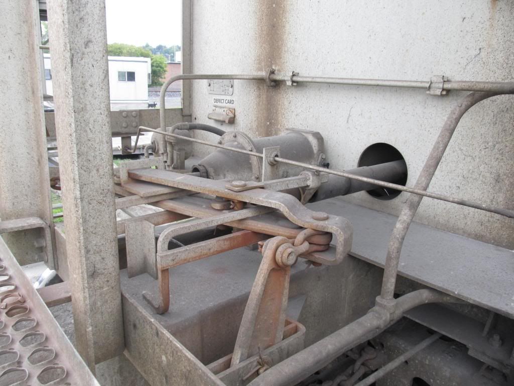
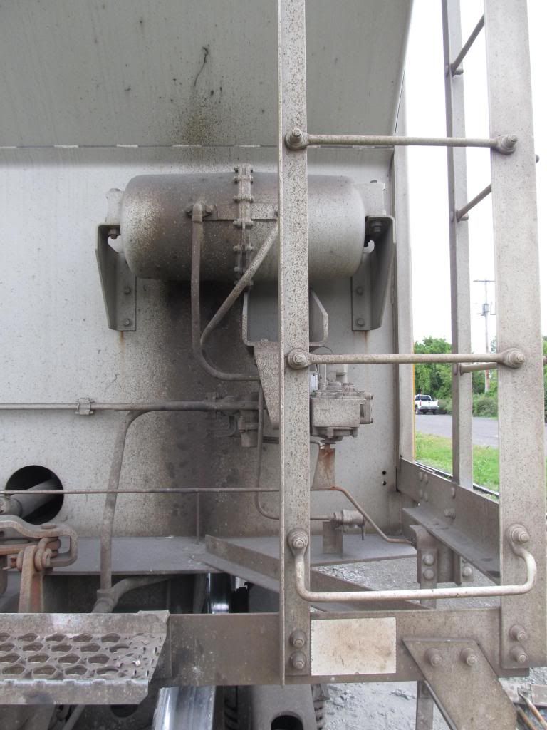
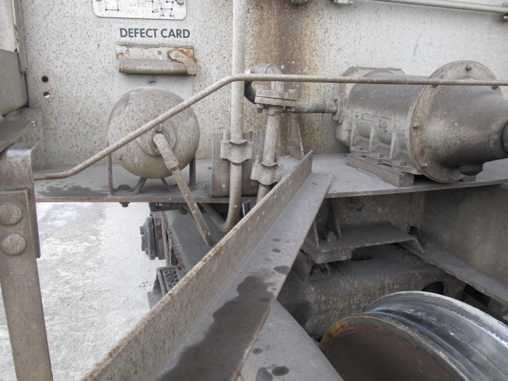
As shown the the photographs that Mark provided, you can see that all the brake components are placed on the ends. Because the doors under the cars need to open, there can be no obstruction to them. Also, the components are placed in the ends to prevent damage to them from the load flowing out when the doors are opened. Some covered hoppers even have the air brake air pipe run along the outside of the sill (frame) to keep it out of the way of the doors, and the load as its discharged from the hopper.
It’ll be a freelanced, single bay hopper for ore, roughly similar to the On30 kit from Boulder Valley Models. Also, it’s supposed to be an early, or at least non-modern, era.
Thanks for the pics. I wonder how much different the hardware from an earlier era would be from this?
Ray,
You might take a look at something like the ET&WNC hopper brake arrangement - definitely not modern.
And a closer shot:
I copied this out of my freight car book:

I got some split cylinder parts from Hartford when I did mine.
Ray, the above from those who have posted is good info. Knowing your penchant for detail try the additional info for a bit of technical knowledge.
http://www.railroad-line.com/forum/topic.asp?TOPIC_ID=12069
and a pic of the ‘K’ brake equipment.

The cylinders can be placed almost anywhere under the car, or at the end of the car. The air line(s) can run under the center sill or along side the car. This was the builders choice, so you can get away with either.
I’ve shown you the two major brake systems that were used, but there were others.With your talents I’m sure you can devise a believable system
This is what I had bought from Hartford: DRGW caboose brake cylinder and reservoir set (disconnected)
Thanks guys, this is all very helpful!
Ray,
I am just building a pair of Hartford old wooden ore hoppers which also have the brake equipment under the ends. The instructions include a bunch of plans - not one specific to the brake layout, but they show up on various plans of the underside, etc. Unfortunately they are 11x17 so I can’t easily scan them.
There is a good diagram in the bag with the Ozark K brake system - it includes all the parts you need to add brakes to a car. I scanned that one - let me know if you want me to upload it.
Pete
Please upload the K brake diagram you scanned.
Thanks
Tom
Tom Stephens said:
Pete
Please upload the K brake diagram you scanned.
Thanks
Tom
http://freightsheds.largescalecentral.com/users/petert/_forumfiles/misc-2013/Ozark-K-brake-pic.jpg
(They are too big so I won’t convert them to images.)
Pete
Thank you
Tom
Thanks!


