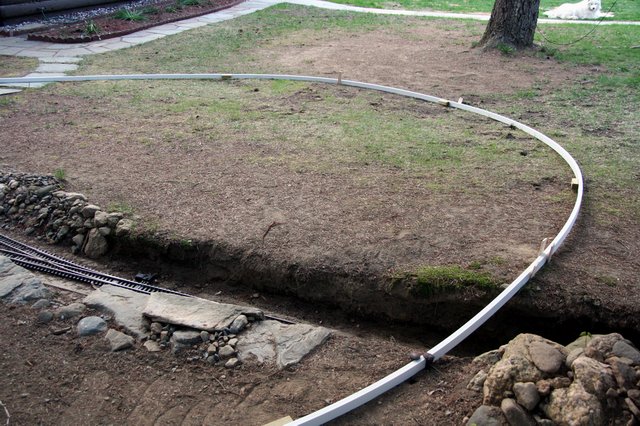
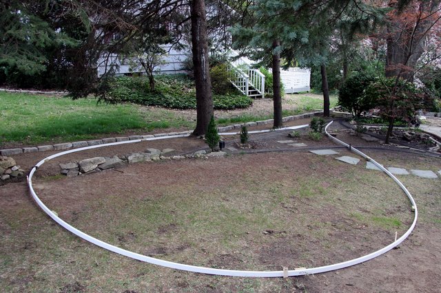
Once again I underestimated how many sticks I would need. 4 more came home today making a total of 64 feet and I’m still 10 feet short of reconnecting to the main :o I’m not sure I’m happy with the shape o the main loop - but this is just a proof-of concept. Before I actually plant roadbed I need to pour pads for the switches, the crossing and bridge abutments. I plan on casting a connection point directly into the concrete to anchor the ladder roadbed. Once these fixed points are established it will be easier to form the roadbed between them. I’m also concerned that the curve back toward the main after crossing the bridge may be a bit too sharp. Since these are free flowing curves, how would you go about measuring the curvature? I thought of using a scale version of an engineering chain and plot the curve in degrees but I’m not sure that’s worth the effort. The latest pictures… Looking down grade from the street [url=lsc.cvsry.com/Expand07-1024.jpg]
(http://lsc.cvsry.com/Expand07-640.jpg)
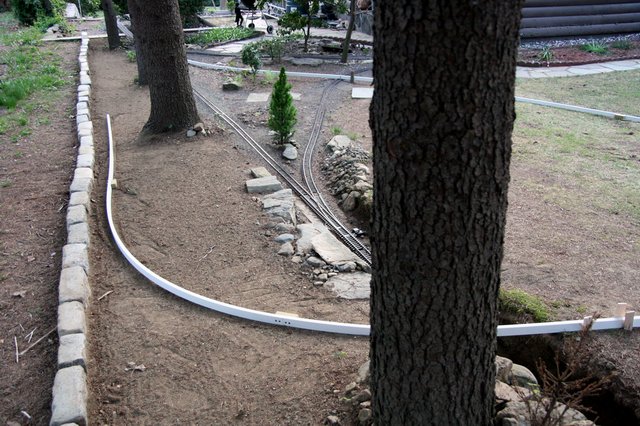
[/url][color=blue]FF: Click to Enlarge - IE: Right Click Photo and select Open Link in New Window to Enlarge[/color] The bridge over deep cut - When built this will be straight [url=lsc.cvsry.com/Expand08-1024.jpg]
(http://lsc.cvsry.com/Expand08-640.jpg)
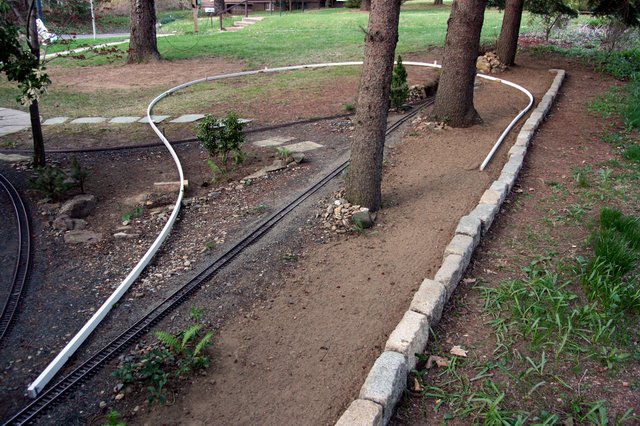
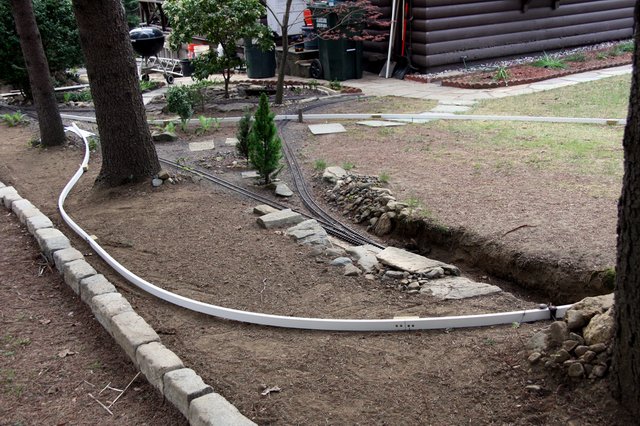
[/url][color=blue]FF: Click to Enlarge - IE: Right Click Photo and select Open Link in New Window to Enlarge[/color] The curve returning back to the main may be too tight [url=lsc.cvsry.com/Expand09-1024.jpg]
(http://lsc.cvsry.com/Expand09-640.jpg)
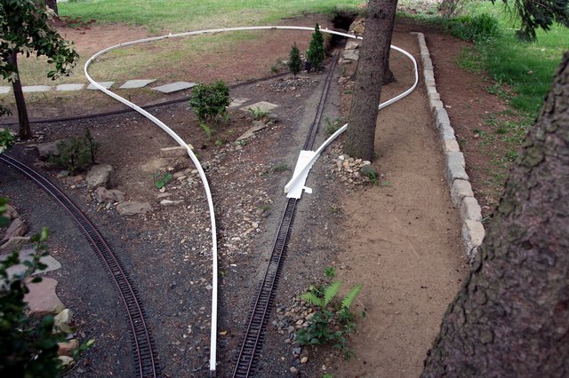
[/url][color=blue]FF: Click to Enlarge - IE: Right Click Photo and select Open Link in New Window to Enlarge[/color] Looking toward the crossing and the bridge over Deep Cut [url=lsc.cvsry.com/Expand10-1024.jpg]
(http://lsc.cvsry.com/Expand10-640.jpg)
[/url][color=blue]FF: Click to Enlarge - IE: Right Click Photo and select Open Link in New Window to Enlarge[/color]