Holy cow, that’s some mighty fine string of switches Neil!
Are you going to pre-fab your track as well?
Holy cow, that’s some mighty fine string of switches Neil!
Are you going to pre-fab your track as well?
Cliff Jennings said:
Holy cow, that’s some mighty fine string of switches Neil!
Are you going to pre-fab your track as well?
Thanks Guys,
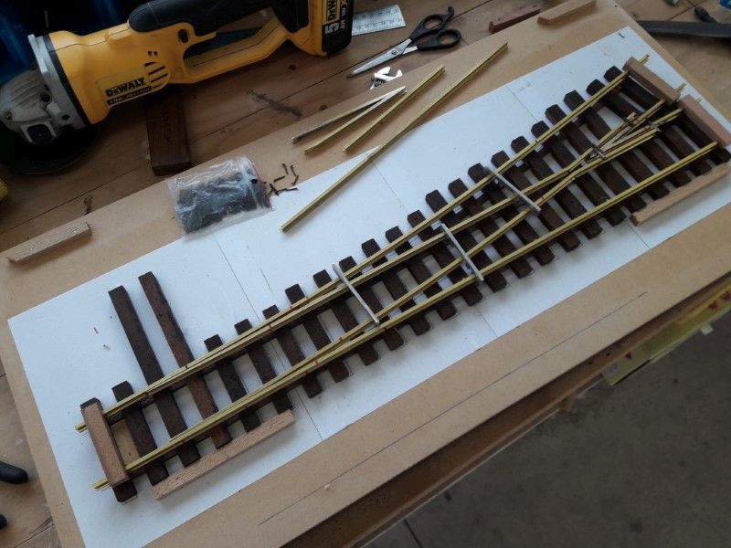
Yep, that is / was the plan Cliff. Once I get one up and working ok I’ll check what rail parts I can mass produce.
The large number is kinda based on Bruce’s comment ‘I always needed one more.’ I took a reasonable number, doubled it - then added two for luck.
Cheers
Neil
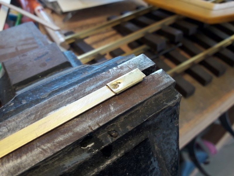
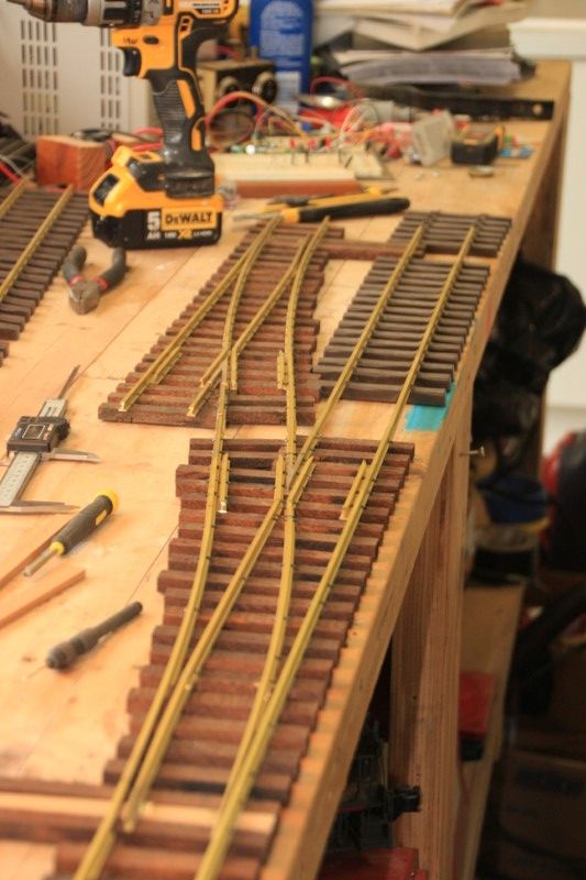
I started on the frogs next. I’d got a bit used to using a grinder for other work so I tried clamping the rail in a vice and having at it, following a marker line. Plenty of operator error, plus the angle being shallow meant the first one needed a lot of hand filing.
Plan B - using a belt sander. Waay better. 100 grit seemed to give a controllable cut rate, with not too bad a finish. Then quick tidy up with a hand file.
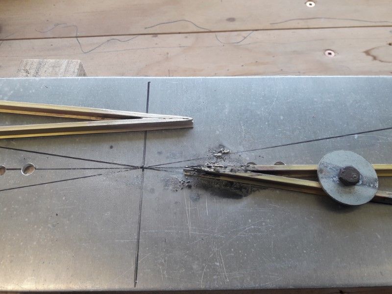
I used a piece of Aluminium sheet with sharpie lines at the right angle for a soldering template, clamp the rails in place with a bolt & washer, then hit it with a gas torch & silver solder. Pic shows #1 finished, and #2 just soldered. Easy tidy up with a hand file…
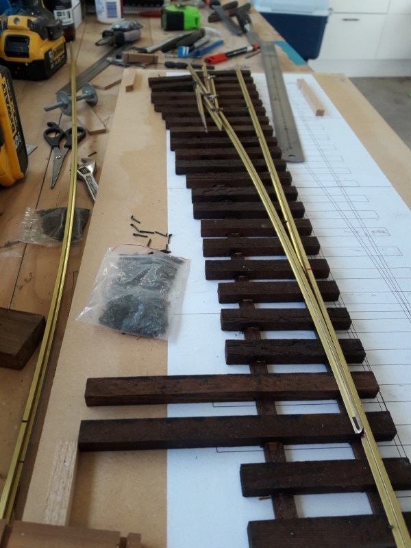
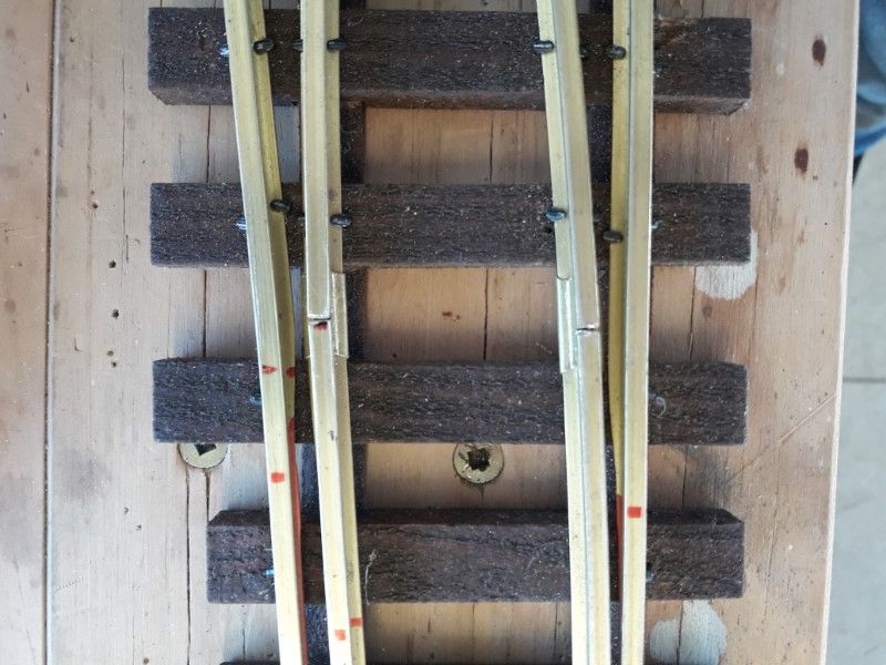
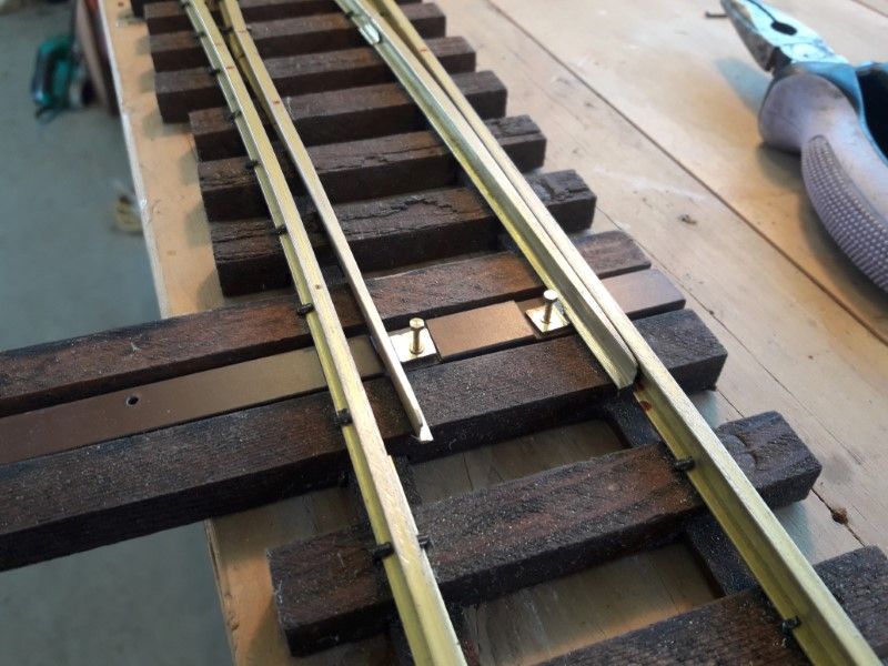
I lightly spiked the straight rail, then the frog, matching the rail drawing for location. The spacers are 3 mm Al bar with hand cut grooves for gauge and check rails. Unfortunately they’re made for 332 rail, but seemed ok at the time, just a little bit sloppy. 20/20 hindsight - this was not a wise choice…!
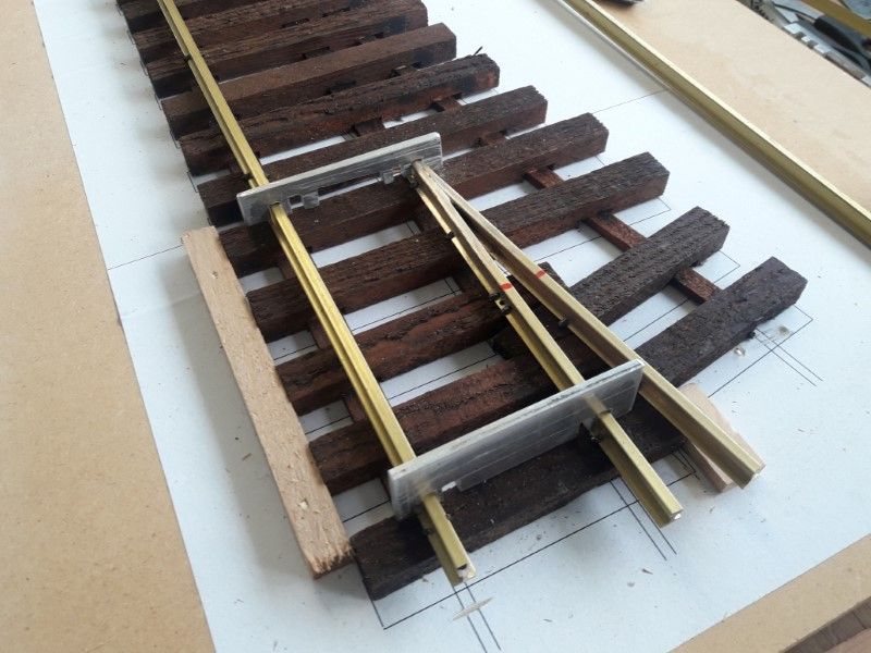
I’m building these to handle track power, although I’m set up for battery at the moment. The red lines and the double spikes on the frog is where the electrical isolation will be made later on.
I’d figured out that the Al rail spacers were giving grief on the clearances by this stage so I hacked out a few wooden blocks that were ‘better’. Pure luck that my table saw blade had a cut the same width as the rail head.
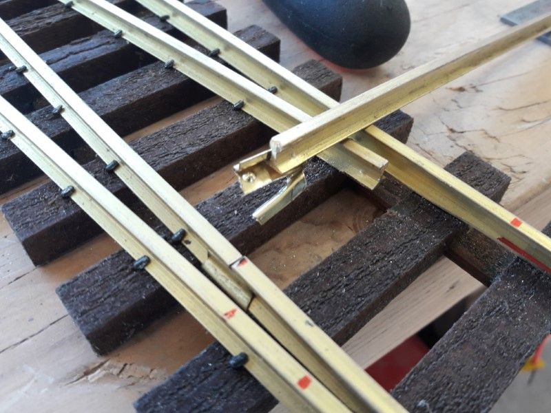
I bent up the curved stock and closure rails next with a railbender. I marked up where the straight rails had to start & stop so I kept a straight section through the frog.
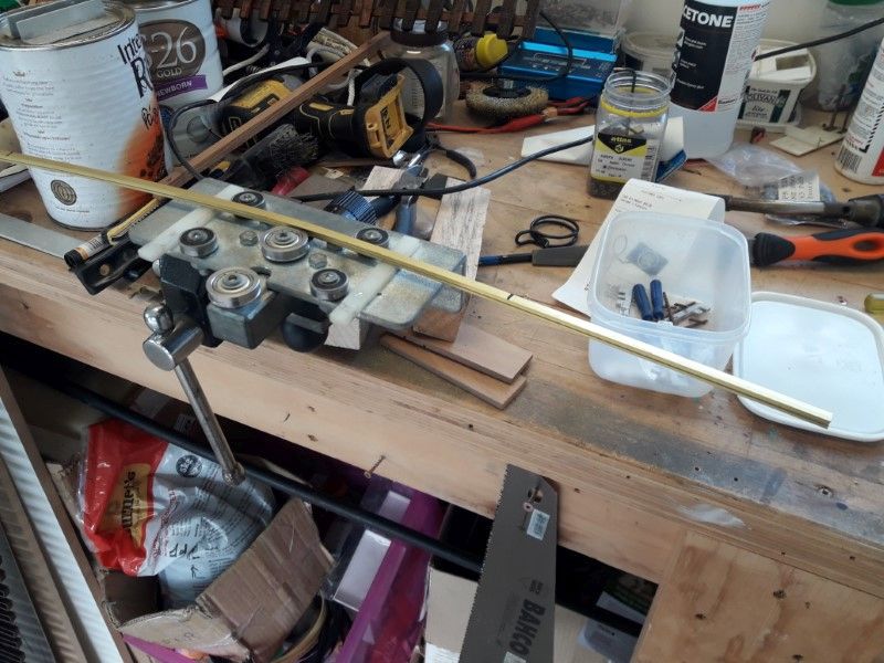
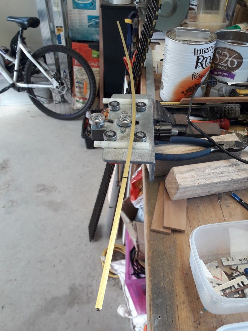
There was quite a bit of trial and error before I got the closure/point rail sitting in the right spot. I made it in 1 piece at this stage so I knew it would work before cutting it for points, frog etc.
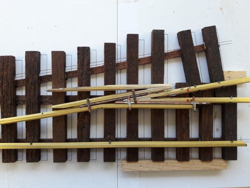
The spacers are made from some 0.101” copper wire, that’s right on minimum G1MRA standard for check rail spacing so it makes a good guide for setup of the frog.
Rinse & repeat for the straight closure rail, and the curved stock rail. Everything was solid rail at this stage i.e. no electrical gaps or hinges for the point rails.
Almost there, last steps to come are hinging the point rails, spiking and electrical gaps…
Cheers
Neil
Looking great Neil. I like the wire for spacing bits(https://www.largescalecentral.com/externals/tinymce/plugins/emoticons/img/smiley-cool.gif)
Thanks Dave.
Day off work today, so I made a final push to get this done.
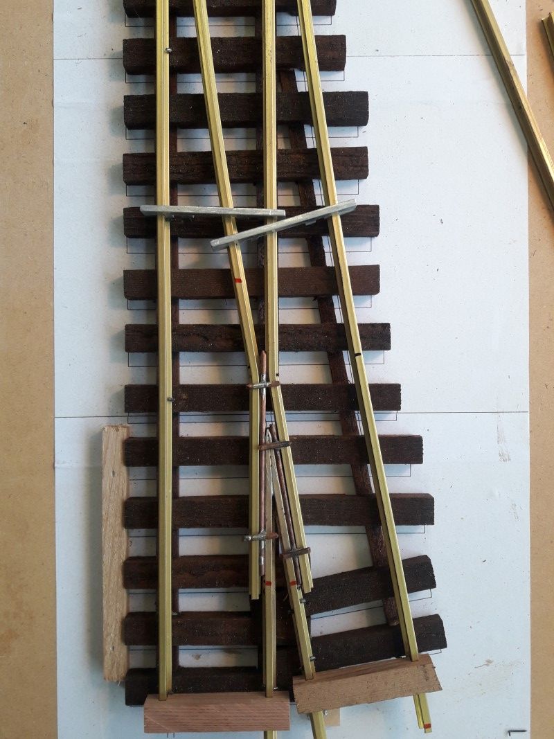
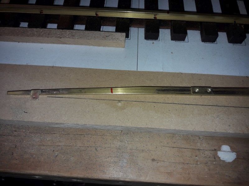
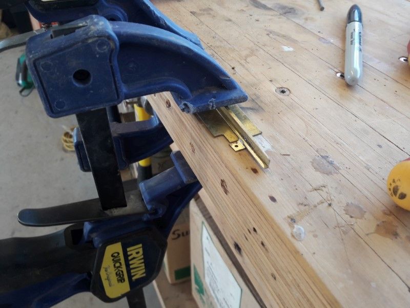
I hinged the point rails by drilling two ‘dents’ in each rail then used half a joiner each side, punching the base of the joiner into the dents. I can’t remember who I pinched this method off, but all credit goes to that unknown person… Then soldered a couple of tabs on for the throw bar.
This got properly tested when I snapped one of the throwbar tabs off right after finishing spiking. It wasn’t quite sitting straight, so a gentle tweak with the pliers… Ahhh crap!

Resoldering in place would have probably made a lot of charcoal. I can only say the pulling the joiner apart with pliers was not a happening thing! I ended up having to file one edge of the joiner apart, then wrenching the point rail clear.
Then reattach, same way as before but in place – with the throwbar tab straight! Only a few minor gark marks on the rail top where I’d tried a screwbar to get it apart.
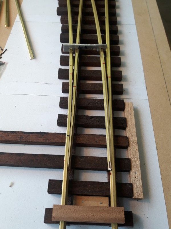
Just the throwbar to go. I’ve got a sheet of electrical formica that seems to stand up to UV really well, drilled and tapped M1.2.
And final testing with a beverage of choice…
1 down, 21 to go… (https://www.largescalecentral.com/externals/tinymce/plugins/emoticons/img/smiley-foot-in-mouth.gif)
Cheers
Neil
Great job Neil.
Good job, Neil…I wish I could do that!
…because my Aristo turn-outs drive me crazy.
Lol, mine did too John.
Cheers Niel…indeed great job, love it
Very impressive!
Hard to believe that you’re making more than 20 of these! I sure hope that covers current and future needs - I found my layout always needed more turnouts than I initially planned for…(https://www.largescalecentral.com/externals/tinymce/plugins/emoticons/img/smiley-foot-in-mouth.gif)
Once again, just beautiful work.
Bruce Chandler said:
I found my layout always needed more turnouts than I initially planned for…(https://www.largescalecentral.com/externals/tinymce/plugins/emoticons/img/smiley-foot-in-mouth.gif)
Once again, just beautiful work.
Or the ones you have won’t fit where you need one. (https://www.largescalecentral.com/externals/tinymce/plugins/emoticons/img/smiley-wink.gif)
Ken Brunt said:
Bruce Chandler said:
I found my layout always needed more turnouts than I initially planned for…(https://www.largescalecentral.com/externals/tinymce/plugins/emoticons/img/smiley-foot-in-mouth.gif)
Once again, just beautiful work.
Or the ones you have won’t fit where you need one. (https://www.largescalecentral.com/externals/tinymce/plugins/emoticons/img/smiley-wink.gif)
Actually, I think it was more like “the ones I built I would NEVER wish upon anyone!” I used to be so proud of them, but Neil’s process and results is probably the envy of ALL of the commercial builders.
I use cedar or redwood, then soak everything in 50% Minwax Ebony Stain/50% boiled linseed oil for a few days. They’ve been in crushed rock for ten years, with no deterioration.
A bit more progress.
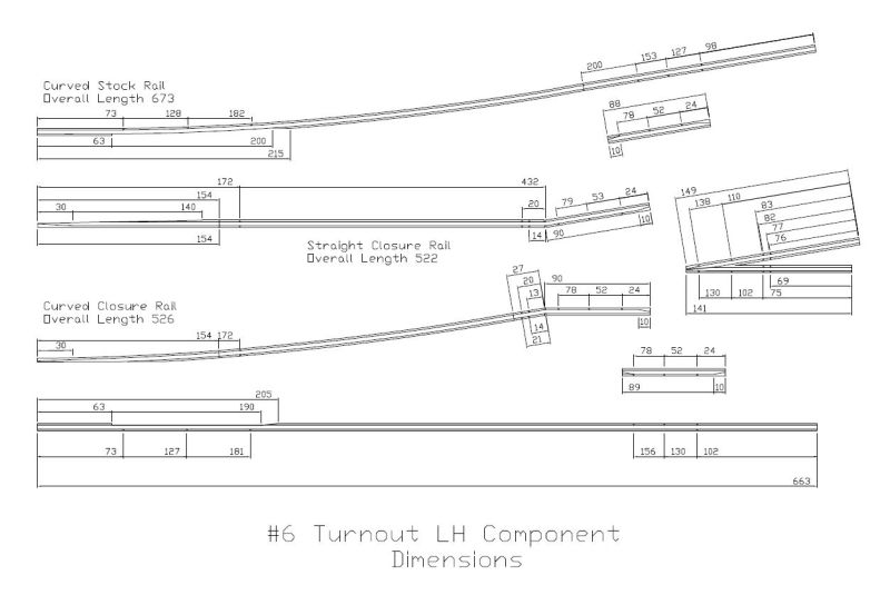
I realised I 'd better do an as built drawing of the turnout to work from, rather than try & do repeat builds from the first sketch. As luck (ha ha) would have it I had a hardware failure on the computer, once I’d got back up and running my old Autocad licence spat the dummy because of a hardware change.
Spent quite a while finding a free replacement - ended up with once called nanoCAD. Major selling point was that it actually opened my dwg files!
Lotsa measuring and fiddling with calipers got me the two drawings below. I’ve loaded both cad and pdf files into my freight shed (Neil W / Turnout builds) if anyone else wants to use them. All dims are in millimetres, Rail is AML/SV code 250.
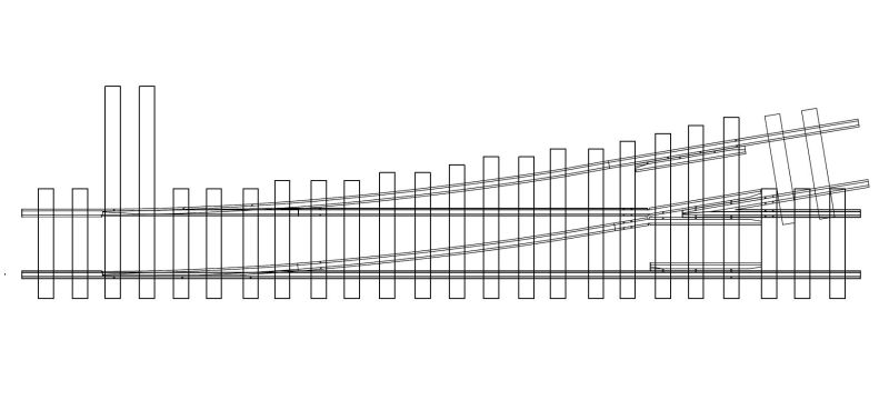
The dots are where I drilled the foot of the rails and spiked thru them. That helps fix the rails from sliding length ways and hold their position where there are gaps. I had to do it for the guard/check rails too as there was no room for spikes between the rails.
I’m gonna try and cut a set of rails this weekend and set if it all fits together.
Cheers
Neil
Neil,
If you have questions, the PRR official drawings are online:
http://prr.railfan.net/standards/
I found them useful, especially for the point blades.
The D&RGW drawings used to be online, but the ‘owner’ decided to sell them on a CD instead, I think. Not before I captured many of them! Most are std gauge, but some are NG.
Hi All,
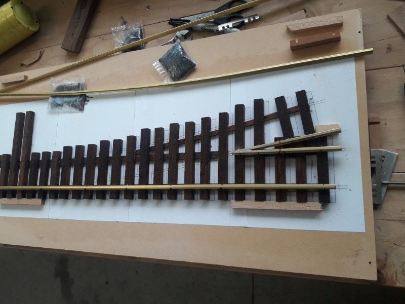
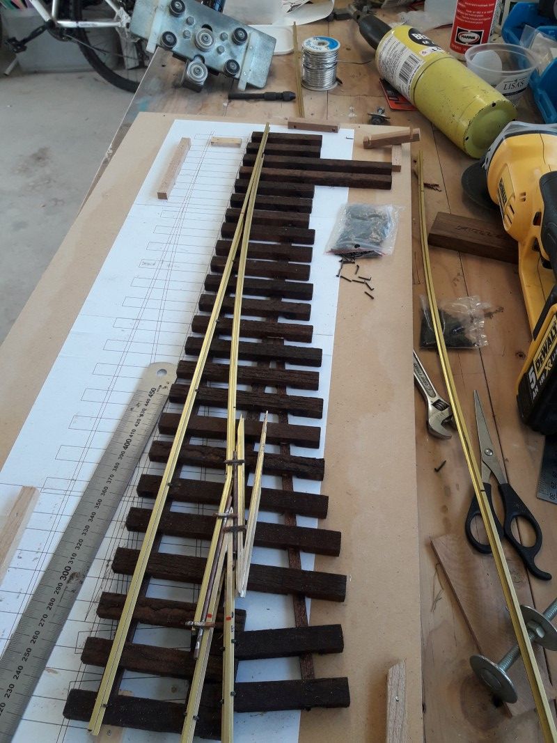
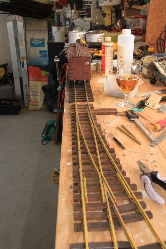
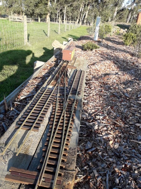
Cut the rails last Sat, and assembled on Sun. Pretty good result. A few measurement mistakes on the curved stock and guard rails for the drill holes but the rest went together as it should.
Rails took about an hour to cut, curve & shape. Assembly took a day on and off around chores.
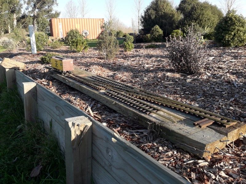
New layout almost feels real now! Took them outside for a photo in the ‘temporarily assigned’ plot yesterday. Lots of work to get this ready but think I can see a passing siding in my future…
Cheers
Neil
Corrected Cad files and pdf templates are in my freight shed. Old files have been deleted…
Cheers
N
Neil Wiggins said:
New layout almost feels real now! Took them outside for a photo in the ‘temporarily assigned’ plot yesterday. Lots of work to get this ready but think I can see a passing siding in my future…
Cheers
Neil
Beautiful raised terrain and background!
Removed … double post for some reason