Large Scale Central

Beating the Boredom - Brunt Coal on the C.V.S.Ry.

Ken Brunt said:

That’ll work. A lot neater looking too.

(And if you did feel like milling more, I have plenty of Spanish cedar and redwood that I could cut a chunk off and send ya.)

Thanks Ken. I have enough Cedar and maybe Redwood to keep me supplied for the rest of my life! I have a few 6x6 chunks about 2 feet long that I keep moving around; and if I ever get back to work I have a lot more chunks of the sign I used for this project squirreled away!

Jon Radder said:

Ken Brunt said:

That’ll work. A lot neater looking too.

(And if you did feel like milling more, I have plenty of Spanish cedar and redwood that I could cut a chunk off and send ya.)

Thanks Ken. I have enough Cedar and maybe Redwood to keep me supplied for the rest of my life! I have a few 6x6 chunks about 2 feet long that I keep moving around; and if I ever get back to work I have a lot more chunks of the sign I used for this project squirreled away!

Hey … Get get back to work …

Jon, I keep asking myself ‘Do you really need the first bents?’ now that you have created the shelf for the girder ends to rest on with the addition of the retaining wall?

Personally I would just make a girder foot for each beam to rest on the wall. If room is needed I’ve seen blocks left out of the top of the wall to create a pocket for the girder ends (https://www.largescalecentral.com/externals/tinymce/plugins/emoticons/img/smiley-cool.gif)

YMMV

Hmm … Hollywood might have a good observation …

I was definitely planning on some type of support for the stringers on top of the wall. Most likely just a wood block. I think I need that first bent for stability, because after the next one there will be a 16 foot gap for the dump bin.

I have some time before I need to decide. Finishing the pickling today and getting the far end wall covered below track level.

With processing of the bents and stringers through the soak and dry process behind me, I moved on to other tasks. The most difficult was removing the AML aluminum track from it’s tie strips. I struggled with that for a long time, but got it done and painted the rail yesterday. I also cut a bunch of these tiny stones with my Dremel to finish off the ends, then mounted it all on a sheet of styrene with E6000. Today I colored the stone with a wash of both the rust solution and India ink/alcohol. This was the result soon after applying the black…

I had previously colored some timbers with the India Ink wash to frame it out. Also glued on with E6000, clamping it up proved to be a challenge, but the chop saw worked out as a holding fixture…

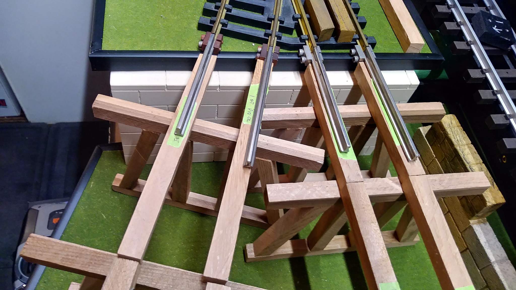
While the glue dries, I switched focus back to the trestle and fabricated up a few assembly tools and did a final dry fit test…

Without the assembly spacers in place…

I have decided that I will assemble each trestle as a stand-alone structure, rather than build it in place. now I need to find a big enough work surface! The dining room table is out as that has become Marilyn’s work-from-home classroom. Weather is supposed to be nice tomorrow, so will probably build outdoors.

Just realized I have completely forgotten that I will also need to color the decking plank. Gawd, this crap never ends!

Jon said -“Gawd, this crap never ends!”

I feel your pain, so many great projects to work on. Hope I never get it all done!

Jon Radder said:

… this crap never ends!

To some extent that’s the whole point of model railroading! (https://largescalecentral.com/externals/tinymce/plugins/emoticons/img/smiley-laughing.gif)

I have put this project aside for the last few days to get outside and take advantage of the beautiful weather. Today will be cool and stormy, so I’m back at it. I’m still pretty much in dry-fit mode as I experiment with bent spacing and alignments. I don’t have a 1:18 dump truck (need to fix that) so an old Ford stands in for a fit test in the dump bin area. My decision to build elsewhere was made difficult by the angular track, so that plan changed to build in place. On the track closest to the edge, the first two bents and the load block on the wall are pinned to the stringers. Everything else is just balanced and my home brew track gauges hold everything in alignment…

The above shots were taken without the bright white LED work light on, this last overhead view is with it on…

Today’s task is to cut some foam and continue the retaining wall along the ramp track leading into McGilicuddy’s. You can see one of my samples placed up against the ties in the last shot. The foam needs to be carved and installed before the trestle to make reaching it easier. The track also needs to be painted and a permanent rest for the photo wall inserted behind the ramp track. Plenty to keep me occupied for many days to come.

Jon, slow and steady always gets it done right. Looking real good.

Al P.

Your Opinion time. Before I begin assemble the trestles I need to finish the retaining wall across the face of the ramp track. When mocking this up with one of my small block samples it looked good with the courses running parallel to track grade, rather than level. In order to be sure this doesn’t look odd I made a full size paper mock up as shown below…

Personally, I think it would look odd, and highly unlikely, if the courses ran parallel to the ground and were trimmed at track level. With them running parallel to the track, one can assume that the balance of the course is buried in the ground. The other way around, a stone cutter would have needed to custom cut every block.

Am I seeing this correctly (trying to model by eye as suggested earlier) ?

If y’all think it looks dumb this way I could always switch to a solid concrete wall with maybe some detail and expansion joints eliminating the courses.

-OR-

I could ask WWTEBTD? (what would the EBT do). The only situation I’m aware of where a ramp track was supported by a retaining wall is in Rockhill Furnace at the coal dock where a concrete wall holds back a portion of the ramp track. However, in Mount Union, a stone retaining wall was used to hold back the street as shown in this photo from 1950…
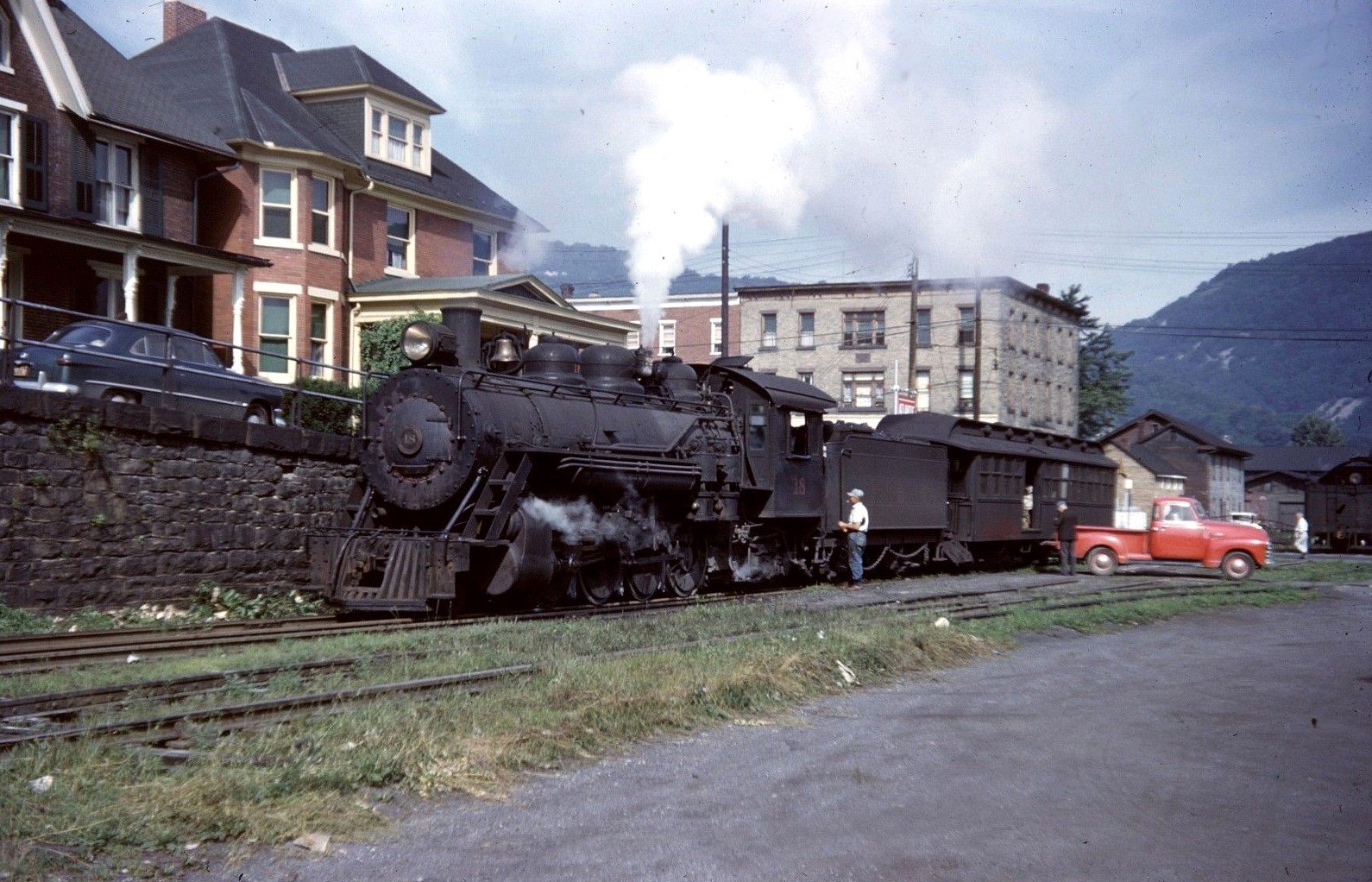
When this wall was built, the stone courses were kept level, then a heavy cap stone was run along at street grade. I wouldn’t make blocks this small as it would increase the labor and not match the other sections already in place. BUT, the capstone idea might work as I’m already using a 6" cap stone on the others.

BTW, besides a mid 50’s dump truck in 1:18 (which has proven hard to find) I also need that Ford sedan and the Chevy pickup!
I think it would look odd, and highly unlikely, if the courses ran parallel to the ground and were trimmed at track level. With them running parallel to the track, one can assume that the balance of the course is buried in the ground. The other way around, a stone cutter would have needed to custom cut every block.

My opinion (as you asked) is that the courses of stone would always be horizontal on a solid base. If they were “buried in the ground” then the foundation would not be flat or level.

The next issue is that your “incline” is probably steeper than any real railroad would use - even the EBT. I think the stonemason would have trimmed the top row/course to match the incline. He might have used smaller stones on top so they would better fit the incline, or maybe the capstone route is the way to go. Your EBT photo shows some smaller stones under the capstones.

Thanks Pete, That’s why I asked. The level foundation reason is a good one. Anyone else have an opinion?

I believe that most likely the courses would run level, whether the ground or top ran level. Therefore in your case Jon the ground is assumed level. Knowing this the top courses would be steppped down in a uniformed fashion, or the stones under the cap stones would be cut on the needed angle at the quarry if possible or cut on sight as needed. Again YMMV (https://www.largescalecentral.com/externals/tinymce/plugins/emoticons/img/smiley-cool.gif)

Oh, and to clear that question :

They would step the footer one course at a time as needed to erect the structure on a hill (https://www.largescalecentral.com/externals/tinymce/plugins/emoticons/img/smiley-cool.gif)

Thanks Hollywood. Yup - if the ground was sloped I’d have known exactly what to do as I’ve built them in the real world, but always with level tops.

I guess it’s time to get out the big eraser and change the angle to under a cap stone - maybe a thicker and longer one than on my other walls, then re-draw the blocks as level.

Flip your paper mock up top to bottom and you’ll have your angle (https://www.largescalecentral.com/externals/tinymce/plugins/emoticons/img/smiley-wink.gif)

Too many straight lines in you’re mock up …just saying and it’s only my opinion …need some irregularities IMO …however it’s only my opinion and either way it’s your RR and what makes you happy.

Looking good !

May or may not help…outdated coroplastic tunnel with the rock wall slope

Rooster ’ said:

BTW …throw the calipers in the trash and model by eye as it works !

Bump for post count