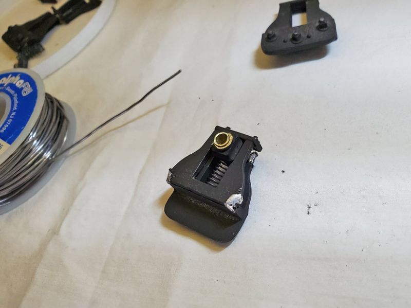
I also have the NWSL gears that I purchased for the same project on my other 3 Bachmann 2-6-0 that also have the split gear. However, for the life of me I can’t figure out how to get the gears on the axel. I can only get them on this far. What’s the trick?
Timmy, that’s not the right gear for that axle. Maybe NWSL sent you the wrong one? Measure the axle diameter over the smooth bit next to the ridges and email them. Maybe even send them the original split gear?
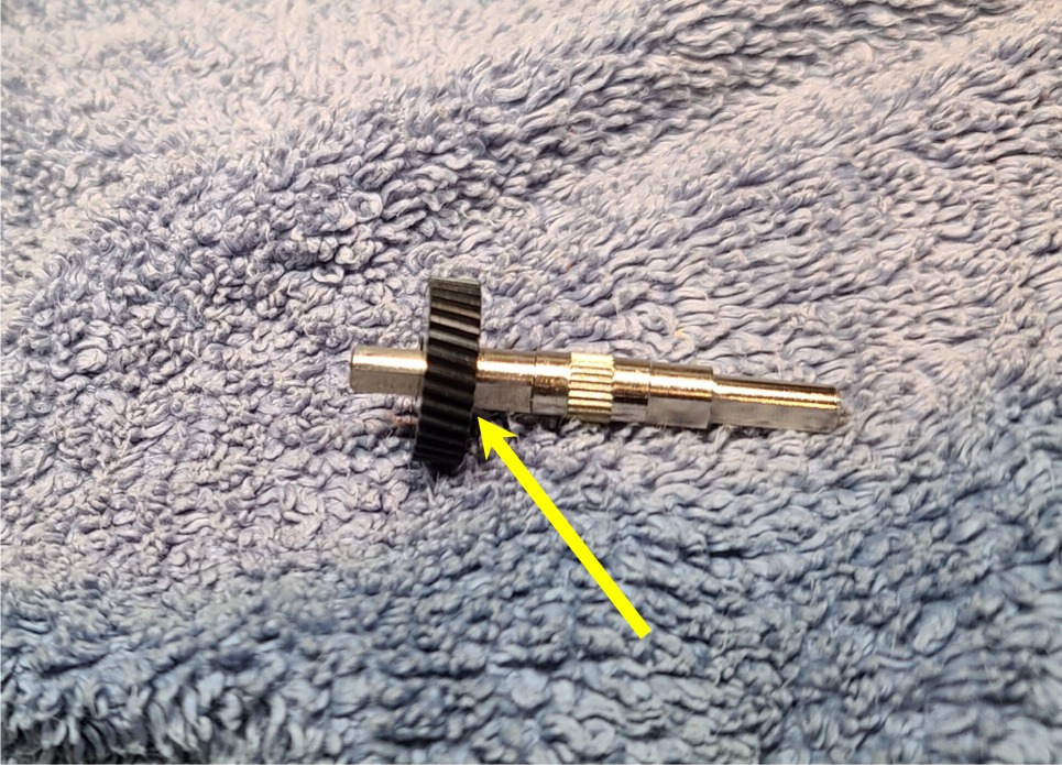
You have a “shouldered” axle which widens where the valve gear slides on. I am assuming that the gear is clearly not going to slide any further past the shoulder?
The NWSL gear is delrin, a type of hard plastic. The “trick” is going to be drilling it out to the right size. For this you really need a vertical drill press. (I bought one for drilling maple cabinet drawer fronts at Home Depot for $90. Many years ago - your mileage may vary.) Or find a friend with a machine shop - a lathe is the proper tool for this job.
If you have a micrometer it will be easy to measure the shaft diameter, but it is probably metric and something like 4mm. Your local Ace hardware will sell you a Xmm drill, or you can buy one online. (If you don’t have a micrometer, now would be a good time to buy one!)
In any case, the trick is to drill a test piece - not the actual gear. Find a drill bit that you think will work and use it to drill a hole in something like a hardwood strip or piece of plastic. Then test that the piece is a tight fit on the axle all the way up to the ridges. Keep trying until it is a close fit. Don’t use an oversize drill thinking the ridges will hold it - if you can’t find something exact, then drill it slightly small and see trick 2.
The gear will have to be held very securely - I use soft wood on either side in a vise or clamp and let the wood grip the gear teeth. You will have to drill very slowly and carefully - don’t press down too hard. It’s quite difficult to drill out a hole in plastic that is almost the right size in the first place, so be careful and make sure the gear is centered under the drill. (To help center it, you can load a smaller drill that fits the existing hole and, with the drill off, press it into the gear while you tighten the clamp to hold it in place.).
If you have drilled out your gear and it is still a bit too tight, then put a round file smaller than the hole in the drill (trick 2) and use it to carefully file (ream) the hole slightly larger. [A proper size drill is a better option! A reamer is the proper tool for opening a hole slightly, but I don’t have one and I doubt you could find one.]
What you are aiming for is a good fit on the smooth shaft and for the gear not to wobble too much when you spin the axle in your fingers. Then you can gently tap the axle into the gear - Michael’s suggestion of small sockets to support the gear while you tap is a good one. I use the vise and put the axle loosely in the jaws so I can tap it through the gear.


