Large Scale Central

Bachmann 2-6-6-2 (no T) Mallet (not Meyer)

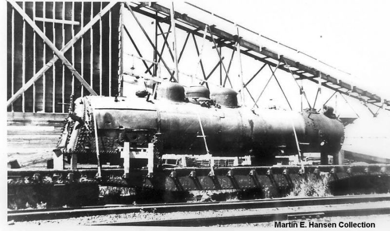
I posted a preliminary photo of this as part of a recent thread on the Aristo 2-8-8-2, but I’m going to start this one so it has its own. When the Bachmann 2-6-6-2T was released, there were a lot of cool things about it … but as the initial reviews showed, some concerns as well. So, when I ordered mine, it was with the idea that it would never really see service ‘as delivered’ and would become something entirely different. The prototype issue is a sticky one in that the model is B-mann’s concept of what a proposed 3’ gauge 2-6-6-2T would have looked like, had it ever been built … but in the case of this specific prototype, never was. At the Slate Creek, that’s not a problem, so long as the resulting model makes sense with the rest of the 1:20 equipment; that is, while there’s no drawing or locomotive to scale down to a model, the result has features and dimensions that make sense. (Please, I don’t want this thread to turn into a re-hash of that weeks-long flap.) To me, the cab on the model ‘as delivered’ would have been a bit uncomfortable (in the real world) for a big fellow like me, and the whole back of the locomotive looks … odd … (It does on the prototype too, incidentally.) So, I thought we’d try a new, larger cab and a tender. Originally, I had planned to remove the tanks as well … there was some speculation that there might be (as with the 0-4-0) an actual boiler under there. Now, at the time, this was a project of such large scope that I’d never have tackled it on my own … but just like the big guys, I found a “Technical Consultant” who could make what I was talking about happen without having to buy more than one of these things. So … this was the original concept:

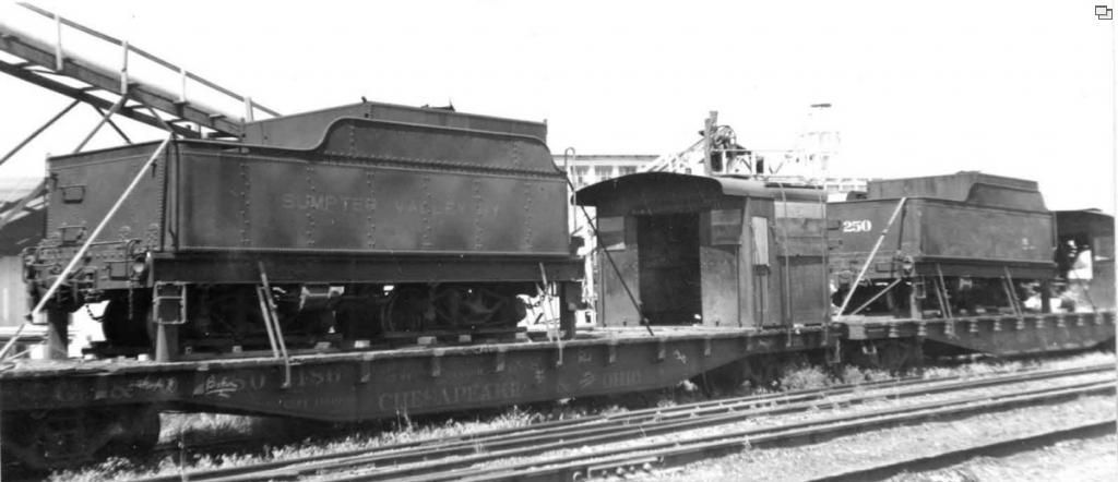
(that’s a hack job of the original promo photo.) As it turned out, there was NO boiler under the tank, and because of the way the floor of the locomotive forward of the cab was constructed, there was no easy way to make one. There’s a great big hole in the middle of the structure (for a speaker) and even at the front, the boiler is not exactly round, being supported instead by a flat section of the rear frame. Also, without the tanks, the boiler is especially skinny, and would make for a very long, narrow looking locomotive, particuarly when it was discovered that the cab, while plausible, would have several dimensions similar to the cab of a Maine 2-footer. With the factory cab in place (and modified, as above) it’d look OK, but once you see the resulting locomotive in perspective with other parts of the 1:20 world, it really is quite a small thing. For it to make sense to me, it’d need a much larger cab … meaning the tanks would have to stay to make it look at all close to proportionally “right.” No really good answers were forthcoming … there were only a couple of similar prototypes with an American outline … and it might really have made sense to just start from scratch instead of trying to modify this particular piece. So, the project stalled for awhile. I called up every photo I could find of similar locomotives, and along the way learned quite a lot about how the real ones work. Ultimately I found this photo of one of the Uintah/Sumpter valley locomotives “mid transition”

Now I know that this was just a matter of a photo taken before the SV shops could remove the tanks … but I’ve seen reports that after they did, there was a weight and driver slip issue requiring lengths of rail and other things to be attached to the walkways … so in my story, the tanks were left both for extra water capacity and added weight. Then came the issue of sourcing the “donor” parts. A B-mann 2-8-0 was located, and the cab and tender salvaged. The 2-6-6-2 rear frame was modified, lowering the cab and cab floor, and a new drawbar system was designed. This locomotive is very different in “layout” than the SV and similar engines in that the boiler is more or less ABOVE the rear drivers instead of BEHIND it … and that made a trailing truck hard to position correctly, as the cab was considerably further forward than it was on other types, and for awhile we considered making a 2-6-6-0 out of it … lack of actual prototypes and a desire to maintain the original arrangement eventually convinced me to decide on a more heavily modified rear frame assemblyto make room for the trailing truck. Meanwhile, from the initial reviews, there was a running gear issue to address. New eccentric rods were fabricated, and the Walshaerts link was modified. The front engine was altered, moving the motor from the middle of the block to the rear, and adding a hinge system that would allow it to pivot from the front engine. The rear engine was fixed in place. As delivered, the dry pipes on the rear engine are in two pieces, allowing it to swing left and right … this was closed with brass tubing, and the rear frame was attached to the lowered cab floor frame. A sliding bearing system was designed for the front of the front engine, where the flat “floor” of the superstructure actually proved beneficial, although some heavy modification was required to make it work. So, the locomotive is now a functional Mallet … this will remove some of its adaptablility to railroads with smaller curvature, etc, but it only has to work here, and all initial reports indicate that it should that nicely. And then, from there, the standard radio/battery conversion, phoenix sound, etc. The locomotive is nearing completion, a project now of some three years … and here’s the first photo that gives the sense of what it’ll look like when finished:

Left to do: The sound triggers are being worked out … they’ll be magnetic ones. The trailing truck is being modified, and then it’ll need some engineering testing to work out any issues. At that point, it’ll be shipped to the SCRY, where the cab details will be upgraded, decals and other details applied, and then it’ll be ready for service! Stay tuned for more photos as that happens. Matthew (OV)

Other considerations of note … Initially, I’d planned to keep the “side door” cab, and make something of a cold-weather cab configuration … unfortunately on most (prototype) designs, this removes the need (and possibility) of the rear overhang on the cab roof. Once you go to an open-deck design (or beyond that to "deckless) there’s no longer any need for a side door. Once it became apparent that an entirely larger cab would be needed to make the locomotive “fit” with its SCRY brethren (again, not saying here that the cab is underscale … but it’d be a REALLY small cab IN scale) the desire for the side door went away, which is really kind of too bad … the SVRY mallets kept their side doors … and the original concept looked pretty cool to me. Here’s an early concept of the “side door cab” idea … note the difference in deck height already rearing its ugly head:

(http://freightsheds.largescalecentral.com/users/slatecreek/_forumfiles/bilesclip.JPG)

The rear of the model as delivered has a frame that’s bolted to the back of the “floor” of the locomotive that slants down and holds the locomotive floor and tender assembly. The bottom of the tender drops down below the level of the deck, and the floor of the cab is quite high. This made for difficulties matching up with the floor of the new tender … and several ideas were considered involving raising the tender off the wheels (which made it look like it was on stilts) or making the tender taller, with a higher coal pocket floor (which made it look ridiculous!) and in any event, now the new, taller, bigger cab was taller than the smokestack to the extent that it made no sense for the rest of the locomotive… so the frame was reversed, now being BELOW the attachment wih the floor instead of above, and lowering it significantly… and voila! The floor now matches the tender deck. That did require raising the backhead structure inside the cab a bit… making the fire door a bit higher off the floor than originally … but that’s fine, and consistant with several 1:1 locomotives you might consider. As the entire cab interior, controls, etc will be reworked, this isn’t a big deal either. The front wall of the cab lies where the original did … what is now the rear beam of the cab (where the drawbar is) was once the front wall of the bottom part of the bunker … significantly lowered! The concept of piston operated suspension to make the front end of the new “low to the ground” mallet hop up and down was nixxed by management. While this is a compound locomotive, and will normally run as one, soundwise, there’s a pickup on both engines, and so (just like the real thing) it will be possible to manually “simple” the locomotive, which was done for more starting traction in some cases, and in the event of a mechanical problem. That really is about as important as the valve gear switching directions automatically on the Shay … but I think it’s pretty cool. Matthew (OV)

Neat project, in the real world, it was Sumpter Valley’s removing the side tanks on the Mallets that hindered them as it severly reduced their tractive effort, if they had left the tanks on they might have survived longer in the US.

Victor, they tried to overcome this by welding rail to the foot boards, but I think that it wa not enough weight. And yes you are correct, they may have done better wher ever they were sold.

Matthew, you done good with one minor thing, a B-man tender is about 1/2 scale inch off the SV dimensions, have a set of line drawings! That is what I will use if I ever get that far!

Paul

Leaving Oregon

(http://i397.photobucket.com/albums/pp52/steamnut1917/SVRy250BakerCityGuatemalaBound.jpg)

(http://i397.photobucket.com/albums/pp52/steamnut1917/SVRyEng250and251tendersandcabsloadedforshipping7-14-47SVRREmlawCol.jpg)

(http://i397.photobucket.com/albums/pp52/steamnut1917/SVRYmalletShip4small2.jpg)

in Guatemala in the 70s…

(http://i397.photobucket.com/albums/pp52/steamnut1917/250_251_Boiler_Esquintlav2.jpg)

Nice find, Mik!
That little dismal is the future D&RGW #50

Built as Sumpter Valley #101 May-1937

To D&RGW Dec-1963
To Roaring Camp & Big Trees Feb-1970
To D&S Apr-1981
To CRRM Jul-1984

E. Paul Austin said:
... a B-man tender is about 1/2 scale inch off the SV dimensions, have a set of line drawings! That is what I will use if I ever get that far!

Paul


Which one … the one that’s on there (2-8-0) or a different one?

More construction things: The floor, before being lowered:

(http://freightsheds.largescalecentral.com/users/slatecreek/_forumfiles/floor1.JPG)

The floor after being lowered:

(http://freightsheds.largescalecentral.com/users/slatecreek/_forumfiles/floor2.JPG)

(The screw that’s displacing things a bit has been modified to be one part of holding the rear engine assembly in line … the reconnected dry pipes are the other two. Once that screw’s out of the way and the modified part is installed, the lower frame is parallel to the deck.) What that does for us is go from a cab that’s too tall:

(http://freightsheds.largescalecentral.com/users/slatecreek/_forumfiles/cab1.JPG)

to a cab that’s about in the right position:

(http://freightsheds.largescalecentral.com/users/slatecreek/_forumfiles/cab2.JPG)

(This view also shows you the raised backhead. I still can’t figure out why the manufacturer put some of the things where they did (valves on the electric gauge light? ) but it’ll be sorted out by the time it’s all finished. For a side view, see the original photo… this is where the cab is now.) The frame modification to allow the front engine to swing in its new configuration, and the reconnected dry pipes:

(http://freightsheds.largescalecentral.com/users/slatecreek/_forumfiles/newchassis.JPG)

The new configuration of the front block assembly (compare to the rear, unmodified block.)

(http://freightsheds.largescalecentral.com/users/slatecreek/_forumfiles/motormove.JPG)

(I think in this photo it’s in position, but the hinge isn’t actually made yet) It’s come a LONG way! Matthew (OV)

Matt,

Great Sumpter Valley pictures of 250.

Matt, what was the procedure on moving the forward motor back? I’ve got something similar in mind, since my plans for turning it into two 2-6-2s didn’t really pan out as aesthetically pleasing as I had envisioned. (Wheelbase a scale foot too short for the loco I wanted to model. C’est la vie.

Later,

K

You might have to check with the “Technical Consultant” :wink:

Greg

He might, at that. The TC (!) could give you a great deal more on the exactly how than I could … though I have some halfway decent photos of the process whereby the block was stripped down to nearly nothing. Basically, it was possible, almost as if there had been a design where it had been considered, to move the motor to the rear of the block frame using existing structures … mostly. Before:

(http://freightsheds.largescalecentral.com/users/slatecreek/_forumfiles/blockbefore.JPG)

After:

(http://freightsheds.largescalecentral.com/users/slatecreek/_forumfiles/blockafter.JPG)

Note that while it looked like this might have originally been part of the intended design, that’s like looking at Dinosaur State Park in Hartford and figuring out what a T-Rex was originally supposed to look like. There was A LOT of grinding, drilling, and other “machine shop” magic that had to happen to make everything fit… which (again) is why I engaged the services of someone actually qualified to do that kind of surgery — this is absolutely NOT my area of expertise, beyond saying “I want to do this …” Matthew (OV)

Here’s the view of the stripped down frame modded for the motor/gearbox:

(http://freightsheds.largescalecentral.com/users/slatecreek/_forumfiles/framegrinding.JPG)

The front of the rear engine assembly is also notched to accept the pivoting front engine at the right spot as well. I do not have a photo of the actual hinge mechanism. Matthew (OV)

Neat idea and projuect. you will have a very interesting loco when you are done.

Incidentally, I took my B’mann 2-6-6-2T and modeled Weirhausser #110 in its current livery Black Hills Central #110. That loco is a standard guage loco, but it still looks good. I had to pry it from the hands of one of the Whitmans (family that owns BHC) when I showed it to them.

Quick note the pic in my signature is of #110.

I think that particular locomotive provided a lot of inspiration for the Bachmann model, in the absence of other prototypes to go and actually look at in person and 3-D… but that’s just my opinion. (Though, I think others have said as much too…)

There will be more photos of the pivot going up later, for Kevin and any others interested… and more as the project progresses to completion.

Matthew (OV)

The pivot:

(http://freightsheds.largescalecentral.com/users/slatecreek/_forumfiles/pivot1.JPG)

(http://freightsheds.largescalecentral.com/users/slatecreek/_forumfiles/pivot2.JPG)

(http://freightsheds.largescalecentral.com/users/slatecreek/_forumfiles/pivot3.JPG)

(http://freightsheds.largescalecentral.com/users/slatecreek/_forumfiles/pivot4.JPG)

(http://freightsheds.largescalecentral.com/users/slatecreek/_forumfiles/pivot5.JPG)

Matthew (OV)

Interesting project!

A great post!

Inspiring, no less.

tac, ig & The Vibona Bridge and Crow Creek Boys

I know there isn’t a lot of technical info here… but I just gotta post this because (as far as I’m concerned) it’s about the coolest thing on the railroad… it’s almost done, and it RUNS. (Many thanks, Sensei!) Matthew (OV)

(http://freightsheds.largescalecentral.com/users/slatecreek/_forumfiles/offsetwallpaper.jpg)

Sweet!

More pictures would be sweeter!!!