Experiments & Preliminary Work
Within a few days of owning my Live Steam 2 Cylinder Open Cab Shay I was convinced that an R/C installation was going to be necessary. Even though the Shay is very easy to keep up with and control by hand, the design of my railroad made that impractical. Each run requires the Shay to be turned on a ground level Wye, part of which is in a cut below grade. Reaching the controls on the Shay at ground level and below is no fun.
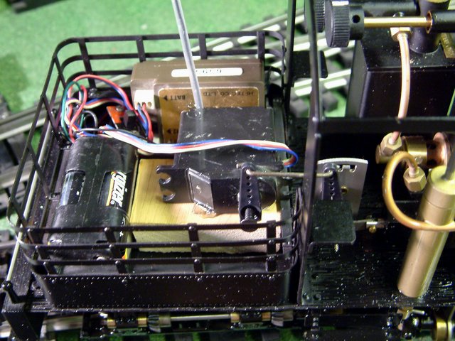
I did some searching on the internet and didn't find much, but what I did find suggested that the Shay would easily operate on a single servo connected to the Johnson Bar. This is supposed to work because Accucraft's implementation of the Johnson Bar on the Shay is actually a valve that has varying degrees of opening. To test this theory I tried manually controlling the speed with the Shay's Johnson Bar. Testing indoors on elevated (but level) track seemed to work reasonably well, so the next step was to see how it would perform outside on the grades. For the same reason that I need R/C to begin with, a manual test of the J-Bar wasn't going to be feasible. The next best thing was a Quick & Dirty installation of R/C using some old (1970's) gear laying around the house. My son Matthew did most of the work shown in this picture.
The entire installation is documented in a thread on Large Scale Central: Quick & Dirty R/C Accucraft Shay Experiment
With the success of the Quick & Dirty experiment, it was time to plan a serious installation. More research was in order that included discussions with Dave Goodson and Tony Walsham. I really like the idea of the RCS system because of the small transmitter size. Dave helped me choose a servo and Tony was helpful at explaining the single-servo version of the RCS system. In the end I was forced to choose an entry level 2-stick R/C system because of budget, but all the work that follows to install this system will easily translate to the RCS or another high-end system.
The Open Cab Shay presents some challenges to hiding an R/C install since it has a very small water tank and a wood rack rather than an oil bunker. I decided early on that I wanted the servo, plus whatever else would fit, in the water tank. On the Mich Cal version of this model, Accucraft provides a hole in the tank for the servo linkage. Not so on the Open Cab version.
To allow for drilling the hole and to make test fits easier, I removed the water tank / wood rack from the Shay. This is fairly easily done by removing 4 machine screws. The screw nearest the butane tank is a challenge because a nut driver will not fit. I ended up carefully using pliers to loosen the bolt.
With the tank removed and the new radio and servo in-hand I began by test fitting components. The radio fit on the available floor space along with the servo, but the tank lid would not close. A second test fit seemed to indicate that the required four AA batteries would fit in with the servo, but only in groups of two. So off to Radio Shack for battery holders. As usual for Radio Shack, the selection was less than ideal so I ended up with battery boxes rather than the open snap holders I had in mind. Back at the shop it was immediately obvious that the boxes wasted too much space and would not fit. Razor Saw to the rescue.
I ended up building this L-Shaped battery box by cutting one box short and gluing the two together with PVC glue. A little quick wiring change resulted in a compact 6 volt supply.
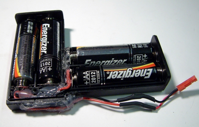
The new battery box just fits inside the tank with barely enough room left for the servo.
Servo & Battery Mounting
Once the battery box problem was solved, the next challenge was how to mount the servo. My son Matthew is a fan of hot glue but I rejected that suggestion due to the proximity to boiler heat. Because the water tank sits directly on the deck of the Shay, bolting the servo to the tank was not an option as there would be no room for the screw heads. The solution was to fabricate a mounting bracket that would attach to the front on the tank. Using some scrap aluminum this servo bracket was fabricated.
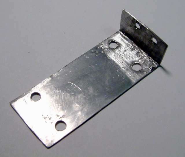
I didn't want the heads of the rather large bracket mounting screws to show outside the tank. I reasoned that nuts would look acceptable since they scale well, but flat or Phillips head screws that large would look odd. Once the servo was test fitted to this bracket it was obvious that reaching the back side of the mounting screws with any type of tool would be impossible. The solution was to use brass machine screws and solder them together with a terminal jumper. The nuts outside the tank could then be tightened without holding the back side.
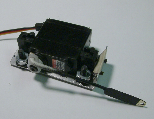
With the servo mounting figured out, the last remaining functional part to fabricate was the servo linkage. My original thought was to use small diameter rod, but looking at the original connection of the Johnson Bar lever to the valve, I decided a small piece of flat stock was needed at the connection point. A quick trip to the hobby store for some brass rod and flat stock resulted in the fabrication of this servo link.
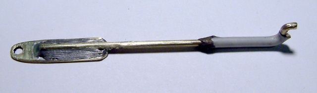
The white covering on the end of the rod is insulation from 14 gauge house wire held in place with a drop of hot glue. It is used to compensate for the over-size bend in the wire keeping the rod tight in the servo horn.
Next the servo link was painted and attached to the servo. The servo was mounted to it's bracket with flat head machine screws. Here you can see the brass studs protruding from the front of the bracket. The masking tape will keep the studs in place until the nuts are attached.
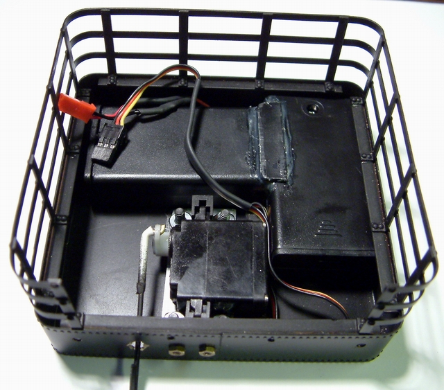
Now the components to be mounted in the tank are ready for final assembly. Here is a shot of the tank with the components assembled before the tank was attached back on the Shay. The battery box just floats; it's weight and shape keep it in place.
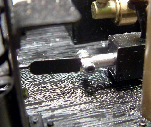
The final step before moving on to the radio is to mount the tank back on the Shay and connect the Johnson Bar to the servo link. I used a 2MM machine screw and two nuts to attach the link to the valve stem. The original brass pin that was in this place was difficult to remove. I wanted a connection that could easily be removed. Here is a close-up of the J-Bar connection.
Hiding the Radio in a Wood Load
The only components remaining are the power switch and the radio. I experimented with mounting the power switch to the wood rack. This worked well, but didn't look very good. I noticed that the handle of the switch was drilled for a control rod. I enlarged the hole slightly to fit the brass rod I had on-hand. The rod allows me to hide the switch with the radio inside a wood load.
I was inspired by some "scale wood" in a photos posted in a LSC Thread by John Bouck. John explained that the wood was Maple branches cut and split with a chisel. I immediately went to the back yard searching for Maple branches both dead (fallen) and live. I picked up and pruned off enough branches to create enough split wood to fill a Delton hopper. The cuts were done on a band saw then split in quarters with a small chisel. I found that the bark on live branches holds on much better. I was able to cut and split dead ones, but the bark comes off easily.
With a supply of wood ready for the load, I went searching for pictures to see how prototypes loaded wood. Did they stack it neatly, or just dump it in the rack? Since wood was abandoned as a locomotive fuel very long ago, there just aren't that many pictures on the internet to choose from. The best one I saw was posted on LSC Chat by Gary Buchanan.
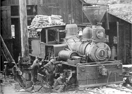
That's one heck of a wood pile! The conclusion drawn from looking at every photo I could find: wood was always stacked, but the stacking patterns were as individual as locos and fireman. Usually the pile looks like it's ready to fall off at any minute.
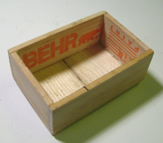
To construct a dummy wood load, with open space inside, I chose to build a small wooden box to support the real split wood. Looking in my scrap box I found some paint stirrers from HoDePo that were just the right height and some more wood that I seamed together to make a top. I tried Gorilla Glue for assembling this box and was very happy with it. Here's an inside view of the box.
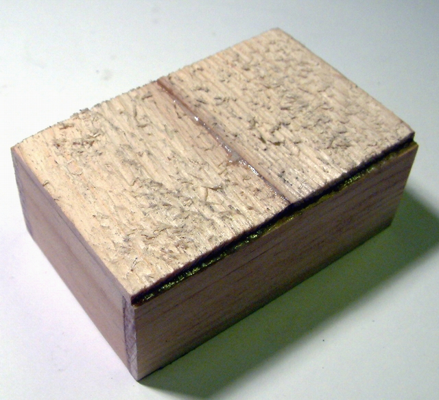
And here's the top.
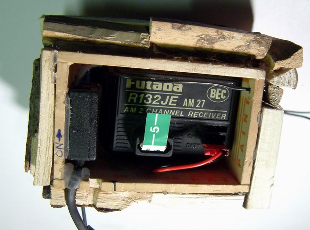
Next I stuffed the power switch and radio inside the box. Both are held in place with hot glue. I'm hoping that they are far enough from the hot metal surfaces that the glue won't melt. I did not want to use a more permanent glue since I plan to upgrade this radio system someday. You can just see the black rod protruding through the box under the wire, that's the on/off switch. This photo is a little out of sequence with this article. It was taken after the wood load was built on top of the box.
The final step is to actually create the wood load and attach it to the radio box. The wood needs to be attached to the box so that the load and radio can be easily removed to access the batteries. There is no provision in this installation for charging the batteries in-place. A charging system is on the wish list.
Finished Installation
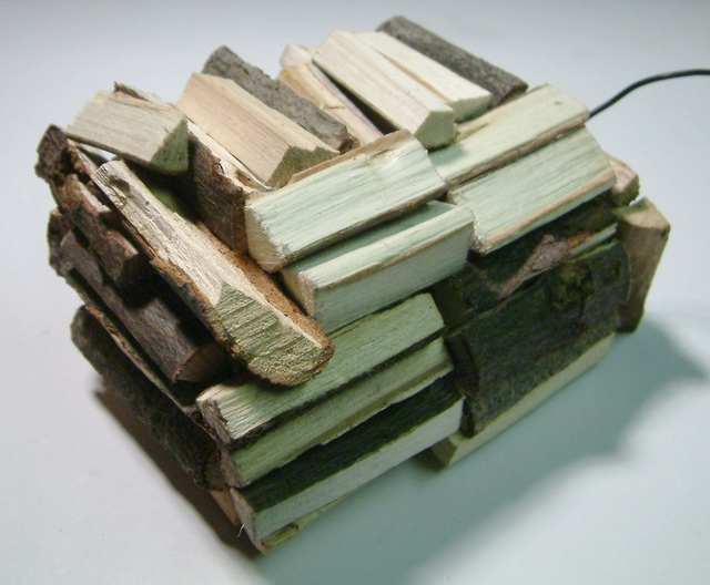
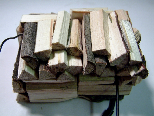
The wood load was made by hot gluing individual pieces of split wood to the radio box. I chose hot glue for its ease of use and ability to bond rough surfaces. I was careful to remove any visible glue drops and strings, but I'm sure I missed a few. Close up photos always point out what you missed. It took some time, but the finished product is believable as a stack of wood. If it weren't for the antenna wire and power rod protruding from the stack you would never know there was radio and switch hidden inside. Several views of the finished load follow.
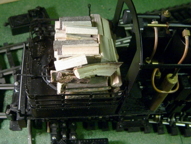
The photos above were taken after adjustments were made. The first attempt didn't quite fit in the rack. Rearranging some of the wood and minor trimming with an Exacto knife allowed the load to fit easily on top of the tank.
With the wood pile fitted inside the rack, the connections between components were made. To eliminate drilling holes in the tank cover, I chose to run the wires through the water hatch. I don't have a plausible prototype explanation for what they are, but I'm OK with that! Here's the load in place and wired up.
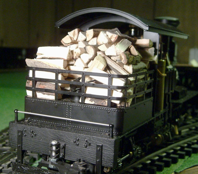
Note the black rod protruding through the back of the rack - that's the on/off switch. Push it in for On and pull it back for off.
I'm happy with the size and shape of the dummy load but it doesn't even come close to representing the huge stacks of wood seen in many prototype photos. I used some left over wood and stacked it loosely around and on top of the dummy load. This helps to hide the on-off rod and make the rack look more prototypically stuffed. The final photo is of the loose wood added to the dummy load.
Next up will be the maiden run of this R/C system. I ran it indoors for a few minutes, with the drive line disconnected, to get a feel for the radio and how it will work. I'm sure I won't be happy with the resolution of the radio system - it's only a few notches from idle to full throttle in each direction, but it will work for now. I'll keep saving my pennies for a radio upgrade. When I'm ready, the servo, battery and radio box that I've built can be used for most any radio system I might buy.
Thanks for looking in.