Large Scale Central

Aristocraft Wiring Diagrams

I am wondering if we still have access to the Wiring Diagrams for Aristocraft Engines. I am specifically looking for the SD45 diagram. I have used these before, but now with the demise of Aristocraft, I don’t know where to look.

My problem is the Track/battery switch on the SD45. I never used the switch, and when I turn on the engine, it won’t run. If I just push down on it, the engine will take off. I was thinking that since I only run track power I would bypass it, and the engine should work right.

Any advice, about the problem or the source of the wiring diagrams.

Thanks

Paul
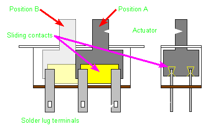
George Schreyer posted some circa 2001 (-2008?) ;

http://web.archive.org/web/20140816111138/http://www.girr.org/girr/tips/tips8/sd45_tips.html#wiring

But reportedly via ‘net chatter, over the years (like all manufacturers) diff. generations of the loco’ meant some design changes (inconsistencies), or blatant factory bloopers !

doug c

If it is in fact the track/battery switch its should be pretty easy to trace out with a meter what terminals you need to bridge to hard wire it to track power.

Paul, there is a website that a fellow modeler has setup as a data base for most locomotives. I am at a loss for his name but happy he has provided this resource, here is the link.

http://www.gbdb.info/details.php?image_id=3184&mode=search&l=english

It has the manual posted and if you use the search feature you might come up with more information.

Steve

2 short jumpers soldered on the circuit board simulating the switch contacts will do.

Greg

Thanks Greg, I had hoped you would see this post. I am electrically challenged, so what do you mean by two short jumpers. Do you mean connect two poles of the track side of the switch. I need to get inside to look at the board.

Thanks

Paul

Paul, take a picture of the top and bottom of the board, and I’ll mark it up for you…

the switch had 6 pins

= = =

= = =

this is a double pole (the two rows) double throw (the left and right columns)

the switch connects the center contacts to one column or another:

=–= =

=–= =

or

= =–=

= =–=

so you can leave it on one position, and solder little wires where I have put the dashes, i.e. connecting externally what the switch SHOULD be doing internally.

if you set the switch to the position you want, then the little jumpers will be “under” the switch handle.

Greg, Here is a photo of the board. The switch is actually stuck in the track power position, but it don’t work so good. I think I basically understand based on your helpful drawing. The pins are the ones on the far right. So should I connect the middle ones to the upper ones.

Paul


20mb image hosting

Here it is only bigger.

Looks like that switch got fried. The soldering flux should be the same colour as on the switches beside it.

These are probably the same switches that were used on the 27 MHz Trackside receiver. We originally used these receivers in trailing cars with batteries packs to power and control our locomotive. The switch was used to turn on and off the battery packs. Everything was fine until the 22.5 volt lithium-ion pack was used instead lower voltage ones. Over time the receiver got harder to power, until finally it would not power at all. I assumed that over time the terminals on the switch were blackened or melted with the power arcing. You could hear the snap when the switch was turned on.

We advised our members to add a standard DPDT toggle switch to turn the battery on and off, and just leave the receiver switch on all the time. That seemed to prevent the problem.

It might help Greg if you took a picture of the top of the circuit board as well.

I can do that, but it is just the switch in the track power position.

Paul

I can do that, but it is just the switch in the track power position.

Paul

I can do that, but it is just the switch in the track power position.

Paul


[url=http://postimage.org/]image hosting 5mb[/url

Top of the board. The bad switch is on the far right.

Paul


[url=http://postimage.org/]image hosting 5mb[/url

Top of the board. The bad switch is on the far right.

Paul

The switch in question is on the far right.

It’s solder looks different from it’s neighbors, but this is NOTHING NEW on Aristo boards.

Yes, jumper from the center to the outer pins, 2 short jumpers, mirroring the “desired” position of the switch.

Greg

Paul Bottino said:


20mb image hosting

Here it is only bigger.

Maybe the switch had already been replaced. It’s definitely a different solder job then the other 3 switches. I would clean the black crust off, and try and wick away the excess solder, when I went to jumper out the switch, but that’s just me.

Good advice. This was my first G scale engine bought new 15 years ago. I only have used it on track power, and actually never used battery power ever. I see what you are saying about it looking different.

Thanks Greg and Dave. I appreciate the help.

Paul