Large Scale Central

Another experiment with an inexpensive Remote Control

Good day - I spent some time over the weekend experimenting with several inexpensive RF (Radio Frequency, not Infrared) LED Controller.s I purchased a few of them and found one that may do what was discussed last week.

Specifically it will control the speed of an engine (something small drawing no more than an amp or so) and can be used to toggle a DPDT relay that will reverse the engine’s direction.

Details are on my web page here: http://www.trainelectronics.com/Articles/RadioControl_multi-channel-RF/index.htm

While I would not recommend these little devices for large trains or demanding applications they do work and are fun to experiment with.

dave

Dave,

Thanks for the research and design and development. I most definitely will be playing with this. I have a couple questions. 1) the blue controller is not being used, so could this then be used to power say the head light, turning it on and off with constant brightness independent of the motor? I would assume one could wire in an LED with an appropriate resistor to knock down voltage to a single LED and return to a common ground? 2) now you have designed this around common G scale voltage of 12V +/-. For running critters or very small things how low of voltage do you think it will operate? I am hoping that we can get to 7.4v for very small locos where room for battery is an issue. 3) Related to the last question if we have say an incoming voltage of 12V can we supply the ESC and the Relay with 12v and then on the motor lead apply a resistor that will knock the voltage down to something less than what is necessary to run the controller? I am looking at playing with the Tamiya motored gearboxes and they are all 3v. Can I take the output from the relay and drop a resistor on the negative side like you do an LED and knock it down to 3V?

Also just for clarification. The red is being set to a simple max and min to turn on and of the relay for switching directions and the green is actually providing stepped speed control?

I just read the tutorial again and I think I need a bit more clarification on actual operations. The DIY1 button is for forward running and then the DIY 2 button is for reversing. Also from the video the DIY3 button can be used for stopping. You alternate between the three right? Which up and down button is giving you actual speed control or is this limited to one speed?

Devon - you are correct that you could use the blue channel for lights or other things.

As to running a 3 volt motor, I have not tested the lower voltage limits - I should think you could get to 7 or so volts - will have to set things back up an see - not sure how the low voltage motors would react to higher voltage through a resistor - sounds like some experimentation is in order!

The setup of DIY1, 2 and 3 is arbitrary -For the video I just set DIY1 for medium speed in one direction and DIY2 for about the same speed in the other direction - DIY3 had both the relay and power to the motor off - keep in mind that once you select one of the DIY keys you can adjust the speed and it will remember that speed for the next time you hit it

Just be sure that you get the unit with the DIY keys!

Hope that covers it!

dave

Well for under 15 bucks I can buy a Tamiya motor and play with it. If down to 7.4v is doable then it would work with just about anything most any of us would play with. The only reason I even mention that low of voltage is for battery space on very small locos. The Tamiya motored gear boxes would be very light duty for our use but it would be intriguing to play with none the less and if the whole thing can be powered at 7v and stepped down to 3v may make for a great critter or trolley or such.

Yeah you covered it I think. . . but I am slow with electrical gizmos so I will ask for fear of over simplification but to make sure I do understand. Using your DIY button arraignment when you hit the DIY1 button it goes forward. While traveling forward you can adjust the speed using the up and down arrows (or the speed +/-) buttons? This is giving throttle control? And so where ever it is set when another button is pushed it will return to that speed. If I have that right then I get it.

I guess the only part I am fuzzy on is what we are using to adjust the speed. . . which buttons and under which DIY key. I apologize for being somewhat thick but I am a hands on guy and it takes a bit to get it when I don’t have it in my hand to play with.

Just picked one of these up on ebay for under $3.00 Just FYI

http://www.ebay.com/itm/181931877655?_trksid=p2057872.m2749.l2649&ssPageName=STRK%3AMEBIDX%3AIT

Devon Sinsley said:

Well for under 15 bucks I can buy a Tamiya motor and play with it. If down to 7.4v is doable then it would work with just about anything most any of us would play with. The only reason I even mention that low of voltage is for battery space on very small locos. The Tamiya motored gear boxes would be very light duty for our use but it would be intriguing to play with none the less and if the whole thing can be powered at 7v and stepped down to 3v may make for a great critter or trolley or such.

Yeah you covered it I think. . . but I am slow with electrical gizmos so I will ask for fear of over simplification but to make sure I do understand. Using your DIY button arraignment when you hit the DIY1 button it goes forward. While traveling forward you can adjust the speed using the up and down arrows (or the speed +/-) buttons? This is giving throttle control? And so where ever it is set when another button is pushed it will return to that speed. If I have that right then I get it.

I guess the only part I am fuzzy on is what we are using to adjust the speed. . . which buttons and under which DIY key. I apologize for being somewhat thick but I am a hands on guy and it takes a bit to get it when I don’t have it in my hand to play with.

Once you press a DIY key you can adjust the three colors up or down any way you want - in effect you have full throttle control at that point - when you go to another DIY key it remembers what you had set when you left the other key so you can get back to that setting quickly - keep in mind that this gizmo is designed for powering RGB LED strips and the varying brightness of the red, green & blue LEDs gives different colors - nice that it also works for our trains

dave

OK Dave I got it now. Pretty cool, thank you for working on this and giving us all something to play with.

Could you also elaborate a bit on the other components. I am looking at a website now at relays and I see several 12v DPDT relays of varying Ohm ratings, any particular one? also diodes I see a bunch of 12v diodes which should we be using. Sorry for the electronics 101 lesson but i bet many of us who might want to take up this challenge might not have the knowledge like I do about circuitry.

I am learning though.

Devon - just about any 12 volt relay should work as the unit can easily supply quite a bit of current - I went with a small relay that only draws a fraction of an amp. See the PCB (Printed Circuit Board) relays here:

http://www.ebay.com/sch/i.html?_odkw=dpdt+12+v+relay&_osacat=0&_from=R40&_trksid=p2045573.m570.l1313.TR0.TRC0.H0.Xdpdt+12+v+relay+pcb.TRS1&_nkw=dpdt+12+v+relay+pcb&_sacat=0

Inexpensive 1 amp diodes are A-OK - like these from eBay:

http://www.ebay.com/sch/i.html?_from=R40&_trksid=p2047675.m570.l1313.TR4.TRC2.A0.H0.TRS0&_nkw=1N4001+&_sacat=0

nothing is critical in the circuit

dave

Thanks again. This will be a fun project for sure. Educational and useful.

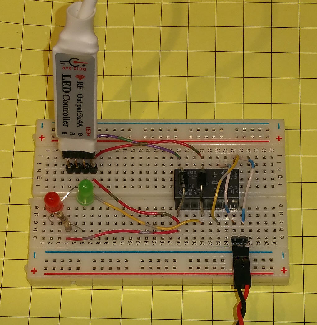
OK I guess I am going to be the one to ask the electronics 101 questions. I was fiddling around wiring this up on a free PCB CAD program and realized right away that I have no idea what I am doing. I would say I feel a little ignorant but I am wiling to bet I am not the only one who might want to do this but does not have the least bit of understanding on how to wire such things. My issue is the relay. I understand that we have a positive and a negative coming from our power source (in my case it will be a battery) into the LED controller (spliced into the big round white wire I am assuming). The that PCB is doing its thing and then has four outputs; A common positive, a red, a green, and a blue (which will have no wire connected to it) which I would understand to be the returns or negatives coming back. That will be plugged into our header. Now here is where I lose it; on the back side we have three wires coming off the header the common +, a red, and a green. At the other end we will have a motor positive and a motor negative (or track if that’s what your powering). In between we have this relay. I will stop here for a second. . .

The relay I think I understand in theory what it is doing. Powered on it has polarity one way (closing one set of contacts and opening the other) and then powered off it reverses the polarity (opening the previously closed one and closing the other). That’s it purpose correct?

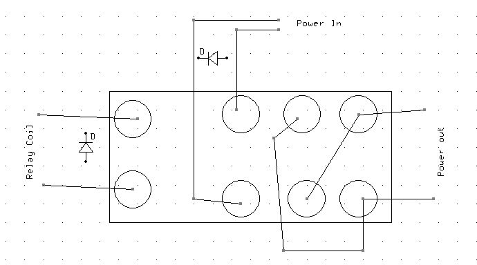
So back to the wiring diagram. Red’s sole purpose is powering on and off the relay. That’s why DIY1 Red is set to max on so it will send full power to the relay. DIY2 Red is set to min that way it provides no power to the relay. So toggling between the two causes the red to energize the relay and de-energize. (just for clarity sake (DYI3 would have everything at minimum so it would effectively be turning the whole works off). In the diagram then I see where the common + goes and feeds the relay and then comes back into the Red return ( I will forget that it goes off to the LED sine that is a visual aid that isn’t actually used in operation); thus completing the red circuit. Now Think I get what it is doing from there. On the diagram where it says NC and NO (twice because it is a Double Throw relay, throwing two switches) and they are separated by a hinged line. That hinged line is representing the switch and the little triangles the contacts right? The Red feeding the relay is causing the relay to throw both of those switches correct?

Now the common + in addition to feeding the relay is also coming into that lower “switch arm” as the + for the motor; and we might consider it the “+ switch”. The green wire which is the motor return of - is attached to the upper “switch arm”, and we might consider it the motor “- switch”. now if I am still tracking in the NC state the right side wire going out to the track would be + and the left wire would be the -; with the NO circuits open. When things reverse and both switch arms drop down (thanks to the red wire and the relay) causing the NO to become active making the right wire - and the left wire +, with the NC circuits open.

So I think I have all that. What I don’t have then is which of the 8 poles on the DPDT relay are going to have what wire attached. Three wires in and two out, where do they go.

Now for the diodes. In the pictures they seem to be integrated into the relay but on the diagram they simply need to connect (directional) between the common + and each of the returns. I am assuming this is done over the top of the relay for convenience of solder connections? Instead of cutting in somewhere else you just crossing the appropriate poles on the relay and soldier both the diode and the wire to the same poles on the relay corresponding to circuit color.

Walking through it I think understand it and just don’t now which leg of the DPDT realy is which. A wiring diagram of that would help and know it is printed on them and I am sure on a spec sheet. So maybe I answered my own question by walking through it.

If I am in error anywhere please let me know.

Now Green is our speed control, we will be using it to actually speed up and slow down the locomotive correct?

Devon - the quick & dirty diagram below should help with the relay wiring - it is a view from the bottom of the relay - the two holes at the left (farther from the next set than the others) connect to the relay’s coil - they get the RED power - a diode goes across them.

The next set of pins (towards the center) gets the power from the GREEN - another diode goes across them

The last two sets of pins are connected with a cross-over set of wires so that when the coil pulls the relay one way the polarity is set one way and when the relay coil is released the polarity goes the other way - just like an old DPDT knife switch.

The rest of your notes appear to be correct. Just resolve to make some mistakes, to kill at least one controller and burn a few fingers and you will be A-OK - we have all been there!

dave

PS - if you look closely at the wiring in the prototype (below) you can see the wiring on the relay and how it matches the diagram in the other email. Keep in mind that each vertical row of 5 connections on the prototype board are internally connected. Also, the top and bottom two horizontal rows are internally connected

Devon,

The DPTP relay has a common ground - the same wire as the ground for the power to the track. So there are two wires out (track power) and three in: relay +/- and track + with the track - the same as the relay -.

Dave,

Nice job - I was thinking the DPDT was the way to go. My question - why the diodes on the relay? Just in case of something?

I found several similar units with 6A circuits, though they are a bit larger! Not clear whether they have the DIY function.

Pete - the diodes protect the Mosfets in the LED controller from back EMF which enters the picture when a relay is turned off and when a motor is spun — without the diodes the circuit will work for a time but the Mosfets would be sure to fail

for more info: https://www.westfloridacomponents.com/blog/what-is-back-emf-and-what-does-it-do/

dave

Devon Sinsley said:

Well for under 15 bucks I can buy a Tamiya motor and play with it. If down to 7.4v is doable then it would work with just about anything most any of us would play with. The only reason I even mention that low of voltage is for battery space on very small locos. The Tamiya motored gear boxes would be very light duty for our use but it would be intriguing to play with none the less and if the whole thing can be powered at 7v and stepped down to 3v may make for a great critter or trolley or such.

Yeah you covered it I think. . . but I am slow with electrical gizmos so I will ask for fear of over simplification but to make sure I do understand. Using your DIY button arraignment when you hit the DIY1 button it goes forward. While traveling forward you can adjust the speed using the up and down arrows (or the speed +/-) buttons? This is giving throttle control? And so where ever it is set when another button is pushed it will return to that speed. If I have that right then I get it.

I guess the only part I am fuzzy on is what we are using to adjust the speed. . . which buttons and under which DIY key. I apologize for being somewhat thick but I am a hands on guy and it takes a bit to get it when I don’t have it in my hand to play with.

Devon - I put my gizmo back on the bench just now and experimented with low voltage operation -

WOW!

It worked clear down to 4 volts! Of course, the relay stopped operation way before that (it is a 12 volt relay) but the motor control worked as did the indicator LEDs.

Might be a good fit for your motors.

dave

Thanks Dave,

Both the wiring diagram and the explanation of how the prototype board works makes much more sense. I am having a bit of fun playing with PCBweb Designer. For me that is how I learn by doing even if i am wiring it virtually. walking through what it is doing helped and now wiring it virtually is getting me right along on my understanding.

Now thanks for testing it down to 4v. that is encouraging, if the LED controller will operate at that low of voltage then by switching out the 12v relay for a lower voltage relay (4v) would allow me to operate this on a 3v motor. I would think the Tamiya motors would take 4v but I am still thinking a resistor to knock it down would need experimentation. In my head I am working on two different scenarios. One is a little loco built likely on a little big hauler chassis that I will operate at the lowest voltage I can that still runs at an acceptable speed; 7.4v-11.1v so this set up you have as is will be great especially at the 11.1v.

The other is just to play with the tamiya motor/gear boxes. I think they might have potential for smaller critters, trolleys, etc and at between 10 and 20 bucks are cheap. As i get comfortable with what I am doing I will play with lower voltage relays and resistors.

Thanks for the help

OK how does this look; I think I have it.

I added a few things to it such as a screw terminal block for all the incoming wires and a master switch to turn the whole thing on and off even thought the DYI3 is turning of the motor and relay it would still have the controller charged right?. This would be on start up and when I am done for the day. I also included a lighting circuit using the blue channel by using the common hot and the blue as the return. Figuring with each DYI button I can have it set to a constant brightness that way forward/reverse/and stop it would always be lit. I have thought of a second switch for lighting that I can turn on or off that way I can leave the settings as is. The two switches would be remotely located somewhere convenient to get too.

This one I figure I would keep simple and run say a 11.1v LiPO or Li Ion attached to a plug that is hard wired to the screw terminal and then I can disconnect and charge the battery remotely or swap them out when dead to keep the battery size as small as possible say 800 mAp. What about a 2amp circuit breaker between the Battery and the switch, necessary?

Once I am convinced I wont blow up my controller or burn my house down I can play with building another, reducing the voltage of the whole system down to 4v for the Tamiya motor.

Thoughts, ideas, mistakes, criticism, suggestions?

Looks good, Devon - A fuse or circuit breaker of some sort is a good idea.

Let us know how the low voltage motors work out

dave