Korm Kormsen said:
…mine looks at the moment, as if the engineer responsable has studied social engineering…
LOL, I like that one Korm. Except that if that were true it would be more, well, colourful.

Korm Kormsen said:
…mine looks at the moment, as if the engineer responsable has studied social engineering…
LOL, I like that one Korm. Except that if that were true it would be more, well, colourful.
more colourfull? - that would be easy.
but really at the moment i’m more after a more “perfessionall” look.
i note, that on your bridge, you alternate the boards in height, that are connecting trestles.
while i had them each on one side above the next board, and on the other below.
now i change that. still up and down, but changing the sides of the ups and downs.
(pic will follow later today or tomorrow)
Noel, even so, i need about 43 ft, to bridge the height difference of about 28".
maybe i should have modelled the San Francisco tram, instead of a wildwest line…
 hmmmm… hmmm… suggestions anybody?
Korm
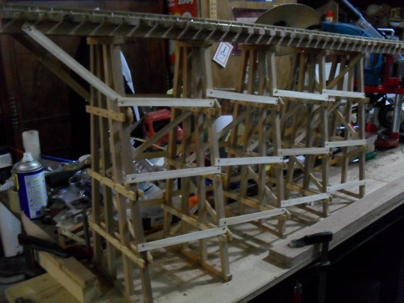
On a staight trestle use the longest pieces of wood you have. When you do attach the longitudinal pieces you should try to span two to three bents if you can. You should also stager jounts if you can . try not to have all your joints atop each other. “see above” When you do attach them they should butt each other ,centered on the bent, nailed at an angle. This is when the pin nailer is real handy. You should use glue also, useing the nails to hold every thing into place untill glue dries.
Note: In your photo all of the diagonals should end @ the adge of the bents uprights. You can see some in your pic. Second bent in pic. good example ! This practice will help you when you go to add the LONG longitudinal boards across each bent.In the below pic of my trestle ,it starts off straight then starts to curve, hence a piece every bent to make a curve, long one in the beginning.
(http://www.largescalecentral.com/public/album_photo/db/aa/01/1a832_20f2.jpg?c=2ea6)
Just kidding you, Korm… It dose look fine guy… But tram…hummmmmmmmmmmmmm. Wooden brakes on them and steep if I remember the Trolley and Cable cars… lol.
oh, btw, Noel, just looked into my mailbox.
Doctors and lightbulbs - that video transmits real pain! hillarious!
but i got something done:
the nastiest part of the project. to get the kerbs more or less similar in inclination.

but now i’m advancing:
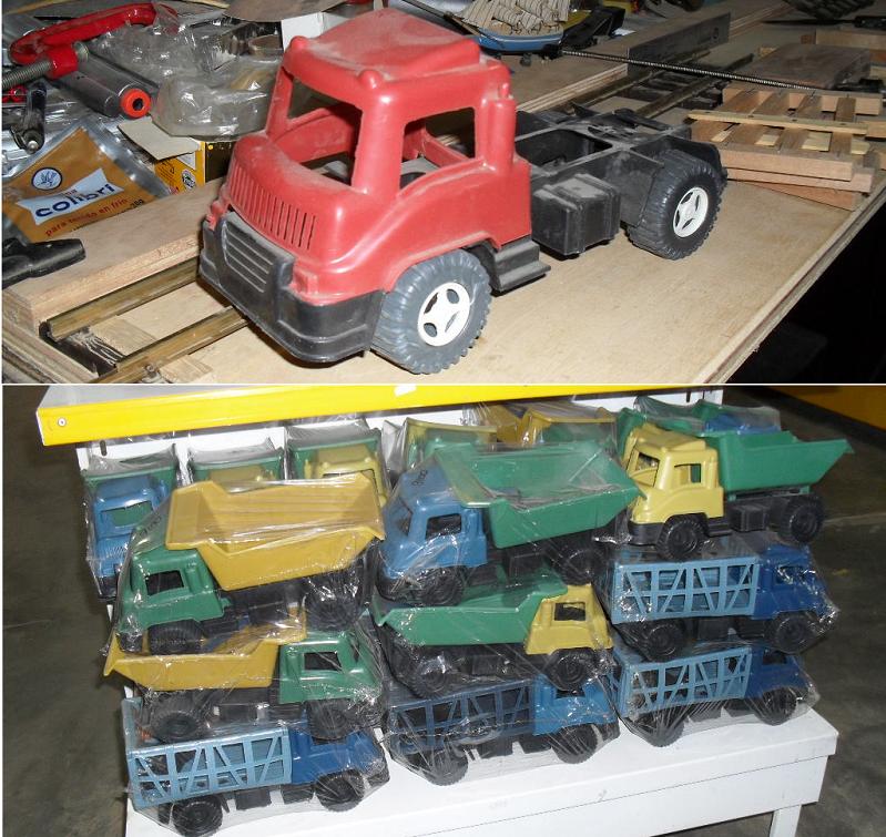
korm…is that what I think I see… A cab over truck cab with morrows on it back behind the trestle? Need a better look when you have time… What brand is it and scale maybe it is.
well, that truck is about 1:22. but nothing to get sleepless nights about.
i just had to take it out of the shelves in the store, because somebody stole half of it.
so it ended on my orderly desk.
this would be better, but a little bit too big.

looked at with bad light, i am content.
that raises a phylosophical question.
for the famous “10 foot rule” (if it looks acceptable from 10 ft, be content)
thanks for all, who councelled me on how to put the boards.
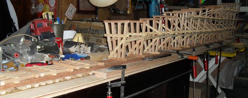
after some tries, i settled for this. the individual boards now are more or less horizontal, while the whole enhances the impression of a steep ramp.

so, the mainpart is done.

now i just have to set the foundations and make one 18" prolongation on the low side.
Seeing it set up like that, it looks real nice.
I agree Dave, I thought it was going on level ground, the slope under it changes everything!
Nice job Korm.
John
thanks for the comments!
this is only a staged mock-up.
i’m still working on the lowside access and the curve on the upper side still lacks a roadbed.


cool beaners
Now that going to be a neat trestle and didn’t now it was going to be that long… Looking good and thanks for the truck pic. Kind of a neat truck to kit bash for a Pig yard lording veh. for USA trailers maybe.
![]()
thanks for the comments.
here comes the last part:
well, the lower part of the bridge is done too.
(i planned it, to be able, to compensate any screw-ups, my height management of the
bridge might have. it turned out, that everything fits fine)
at the very end of the project i had to screw up! the very last tie did split at screwing it to
the beams…
i did, what every second rate wildwest railway would have done - i belted the tie to
another one, that i put beside.

after the last boards been fastened

and the inspector M. Onkey was convinced bei the engineer (soc.) R. O. Oster that a jumping-up-and-down stability test was not necessary

and the crew placed the last tie

the president of the Southern & Gulf helt a moving speech to a crowd of onlookers
(well, yes, that area is very scarce populated…)
in his speech he mentioned, that the last spike on this bridge would be driven in by him personally.
(regretfully, we must admit, that he could not fullfill that. of his crew of cowards nobody volunteered to hold the spike for him)
from the following little celebration (no disturbing food, only drinks), we can not offer any pics, because the photographer had problems with his optics…

