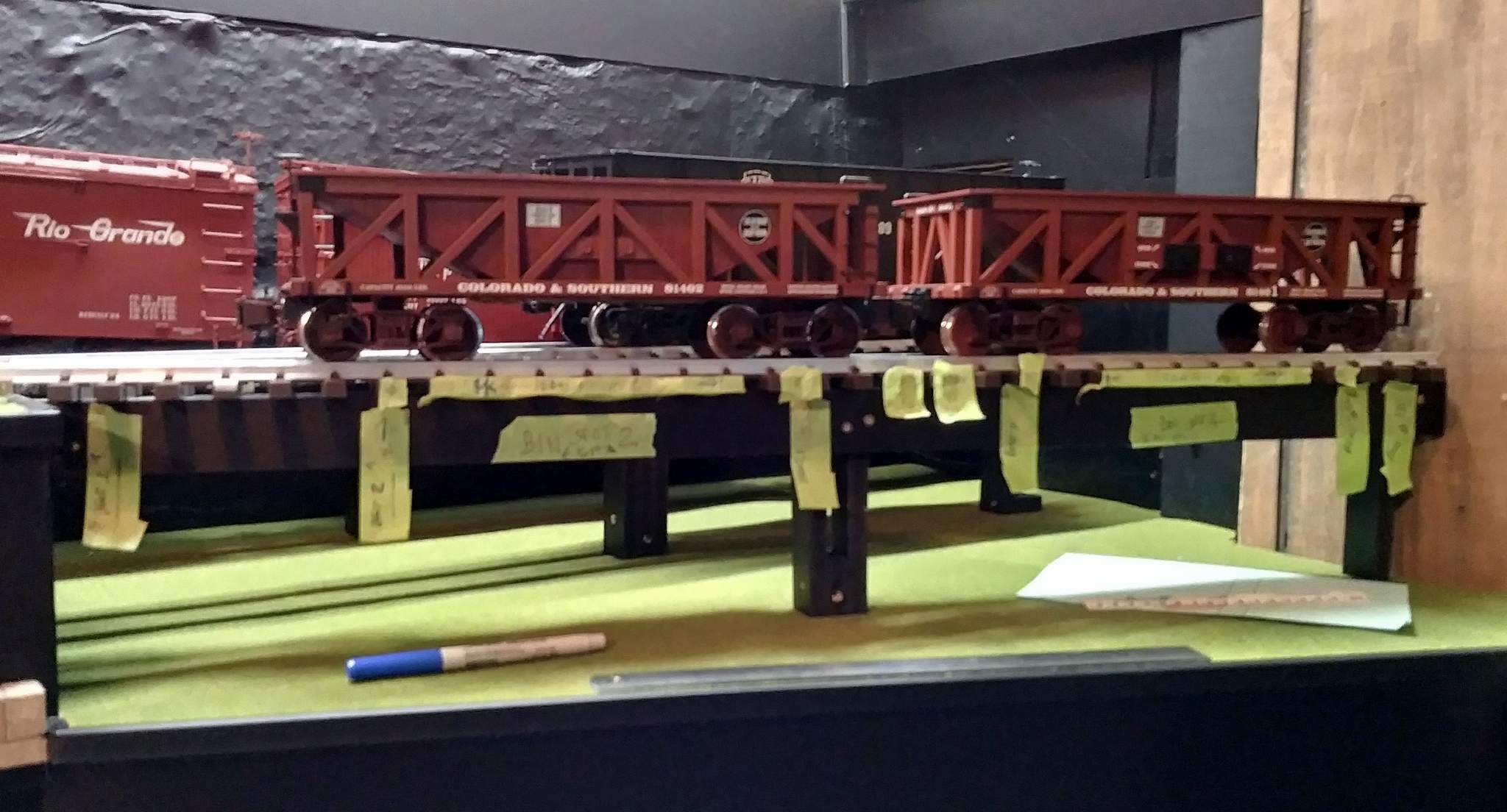
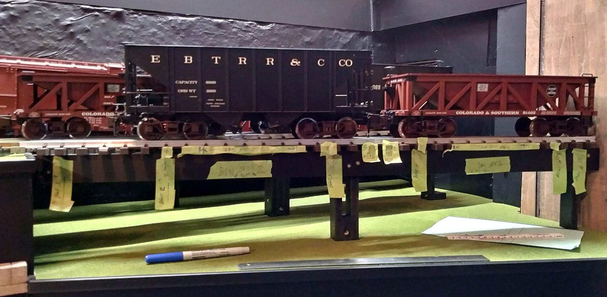
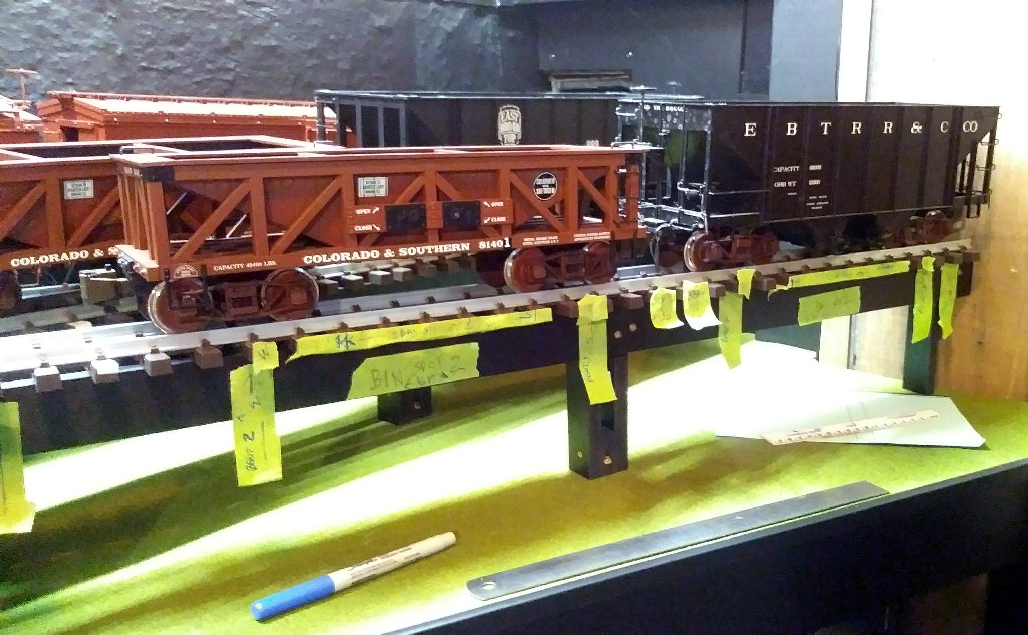
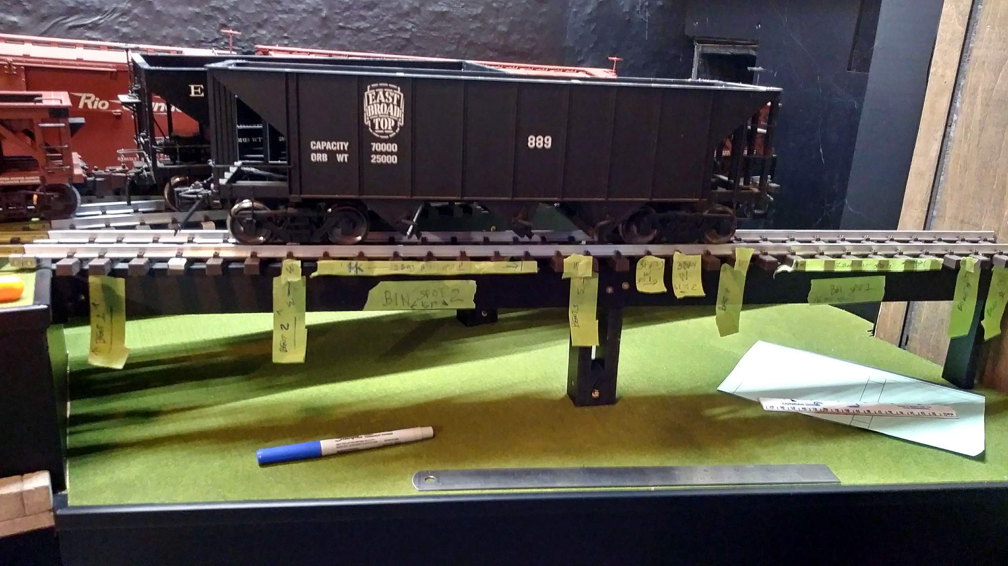
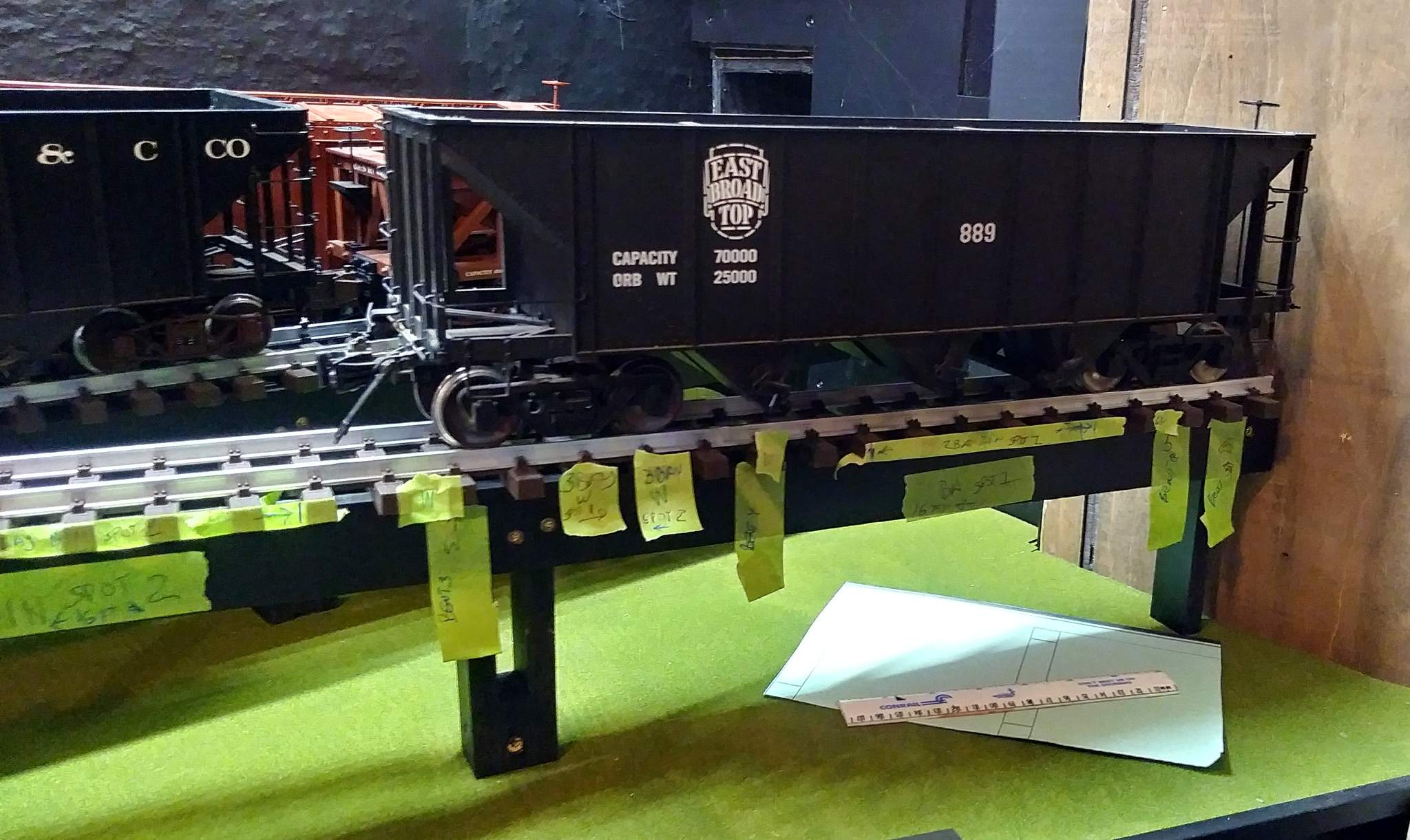
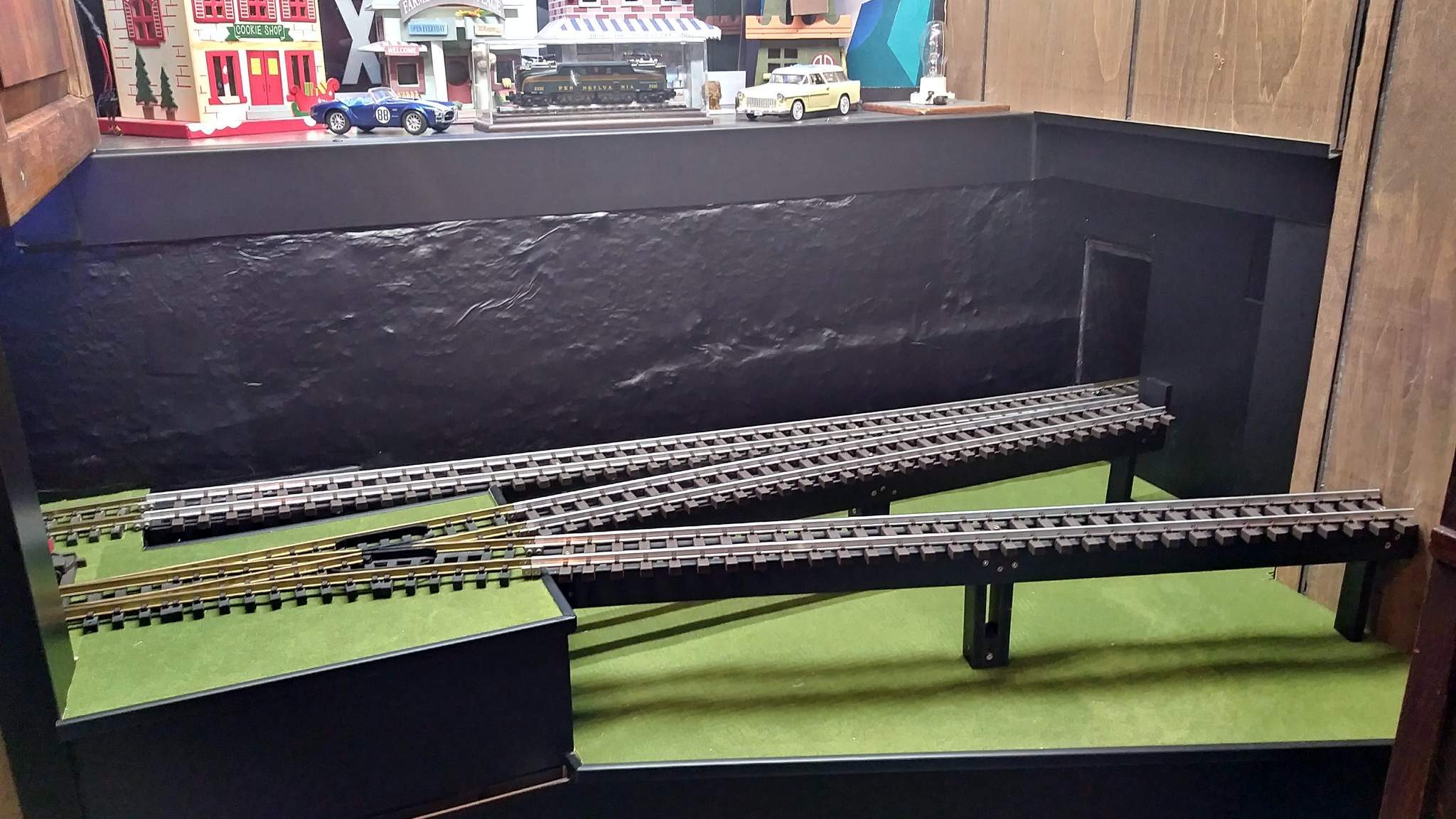
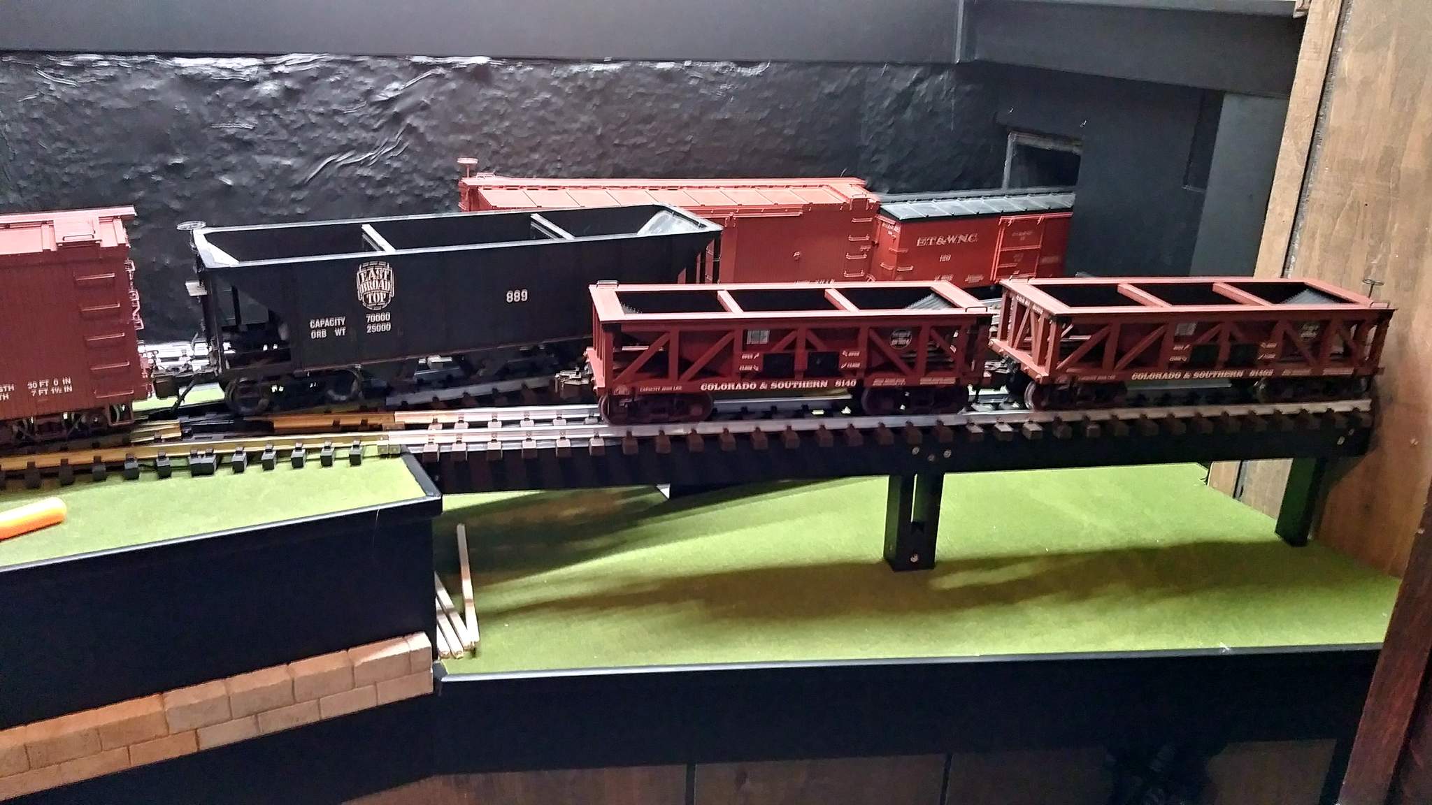
Soon after my indoor expansion at West Willow Hill was operational, the FEBT magazine Timber Transfer published an article by Ron Pearson on the Puckey & Co. Coal and Wood yard in Rockhill Furnace. The coal delivery trestle was a beefy wood structure with a few dump bins that remained extant under different names until the railroad closed in 1956. This structure is perfect for use as my Brunt Coal Co. delivery trestle.
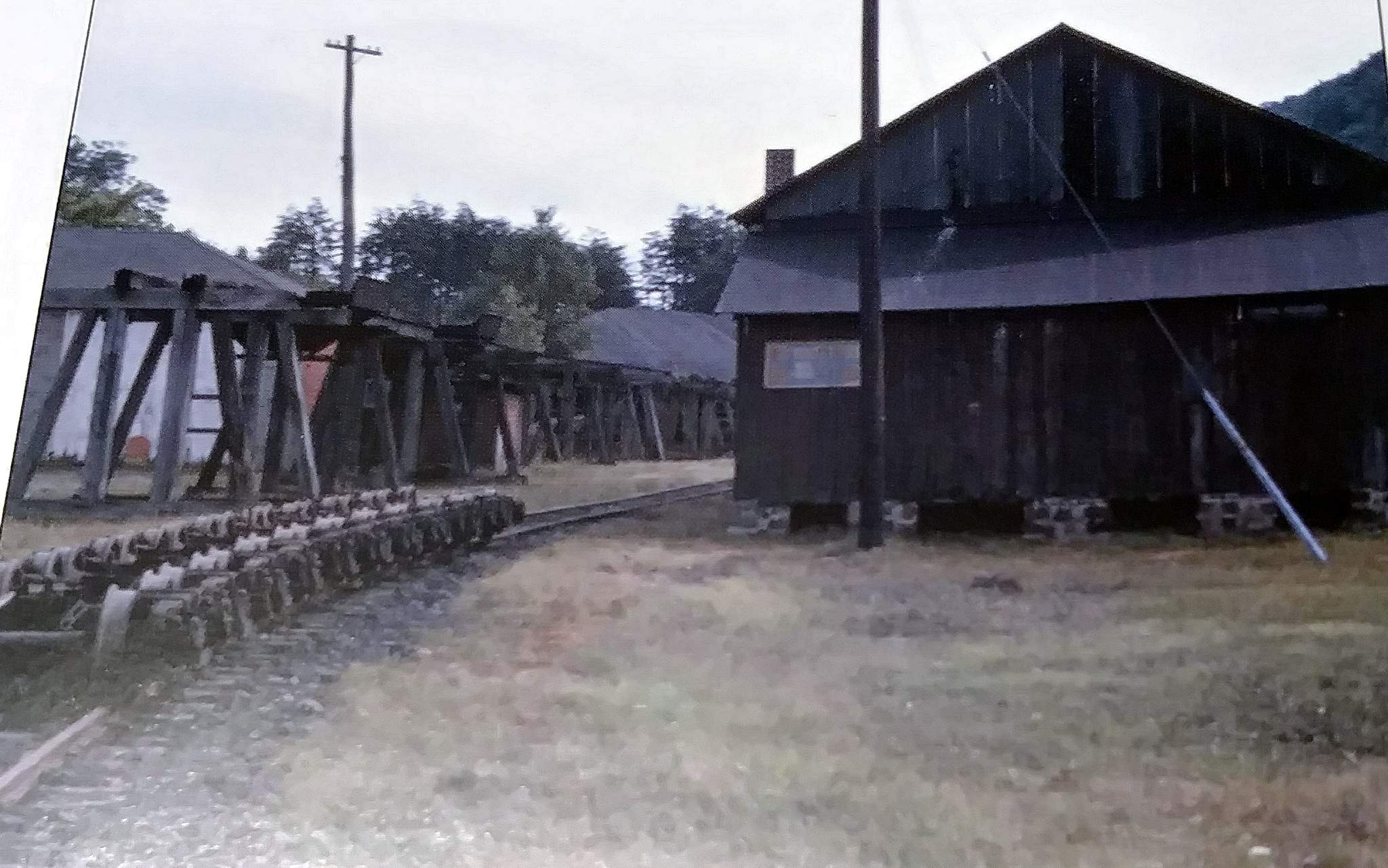
The following two photos of Puckey & Co. stolen from the Timber Transfer article and used without permission. I will delete them if the copyright holder(s) objects…
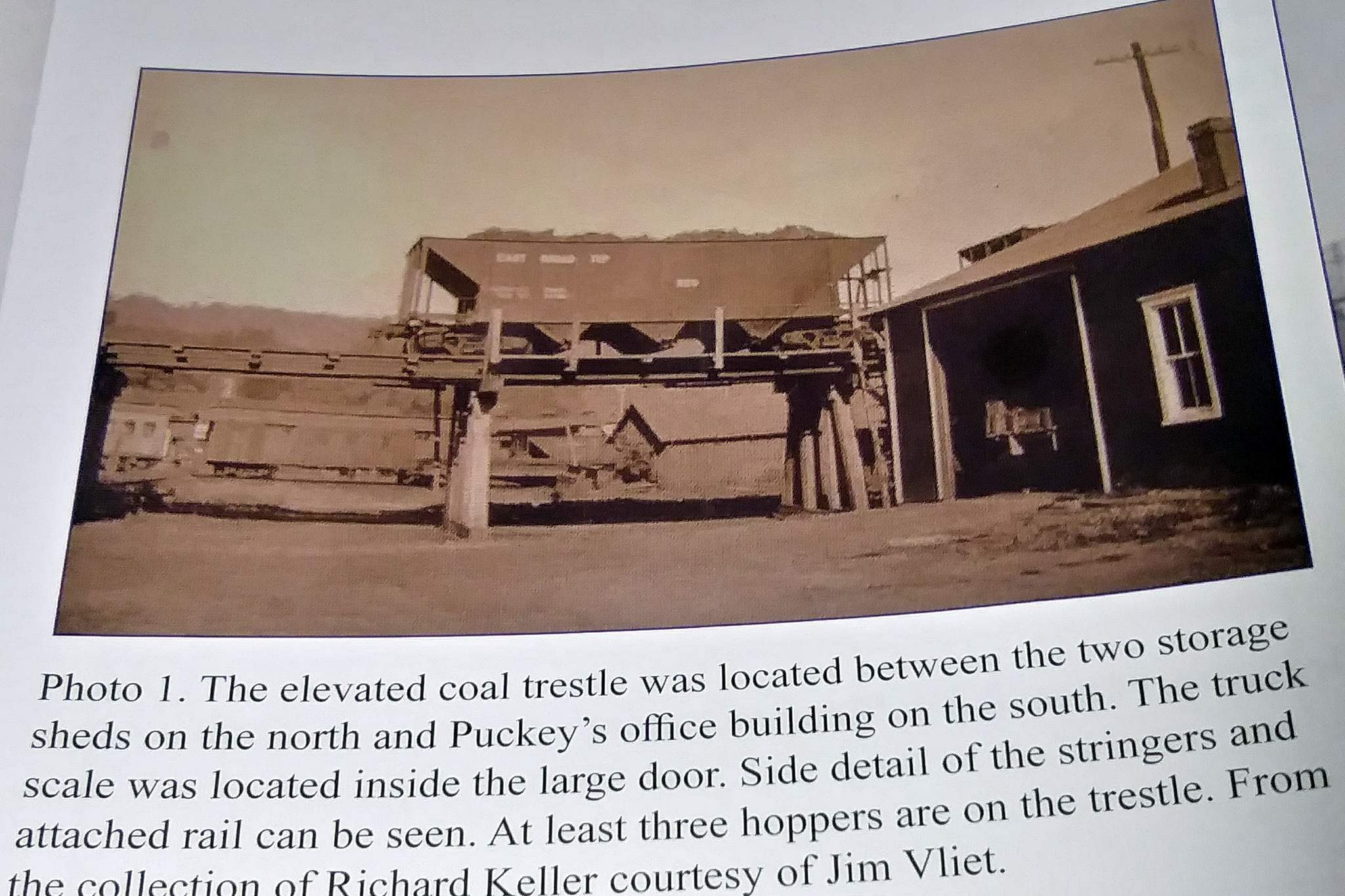
Dave Williams photo…
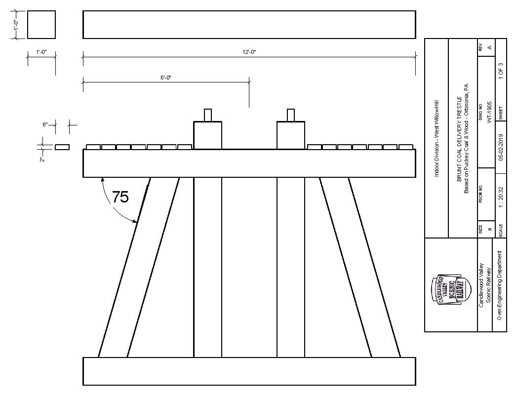
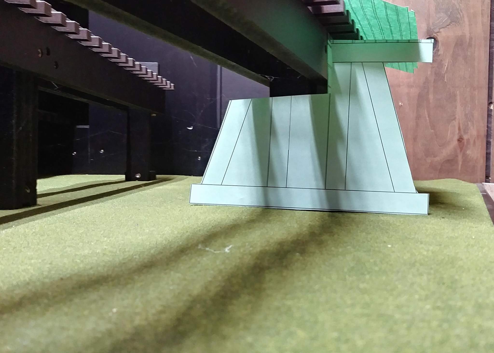
Ron’s article included some scale sketches which I re-drew in Visio to 1:20.3 scale…
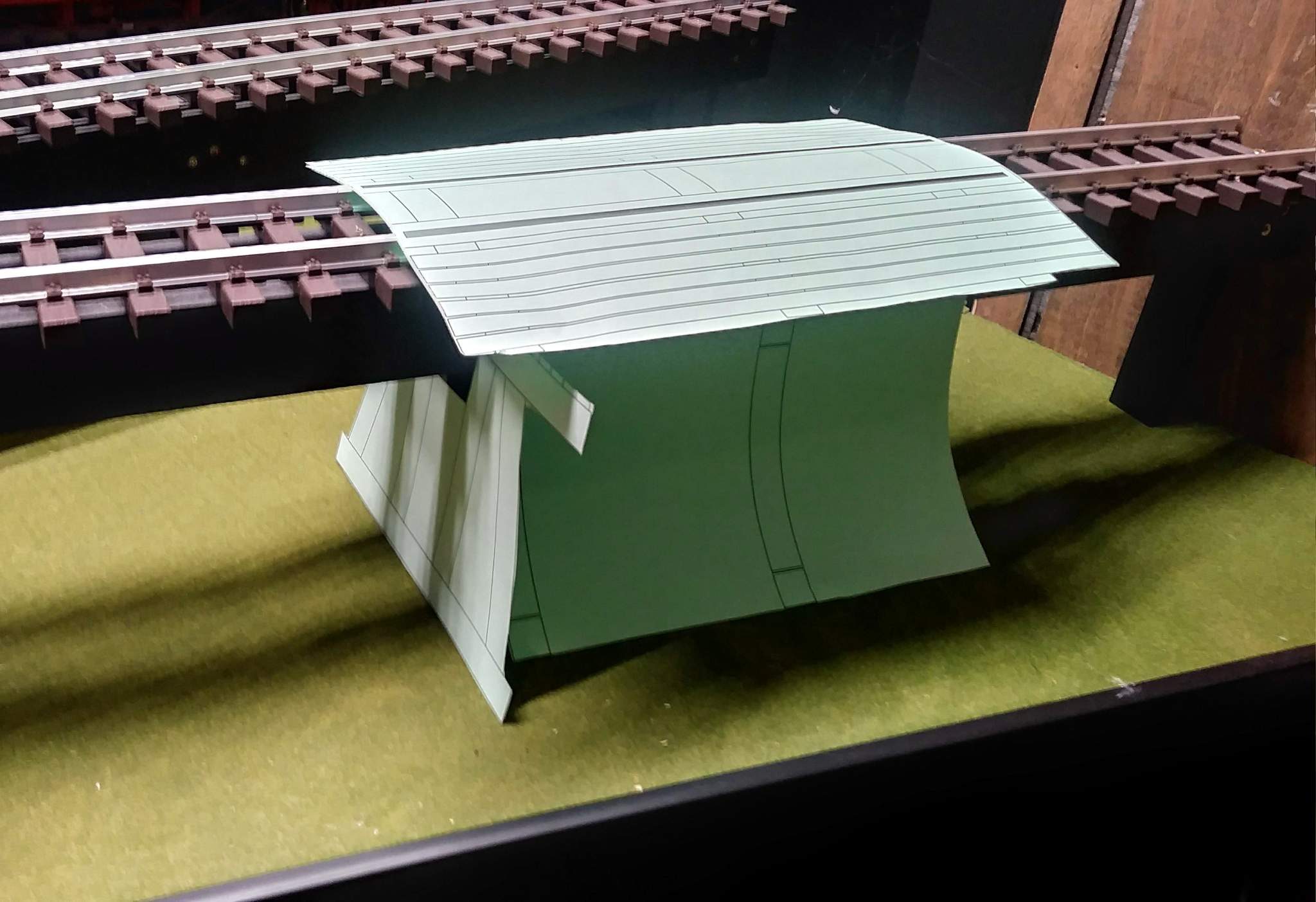
I printed a paper mock-up to get an idea how it might look…
And that is were the project sat for a year; until today.
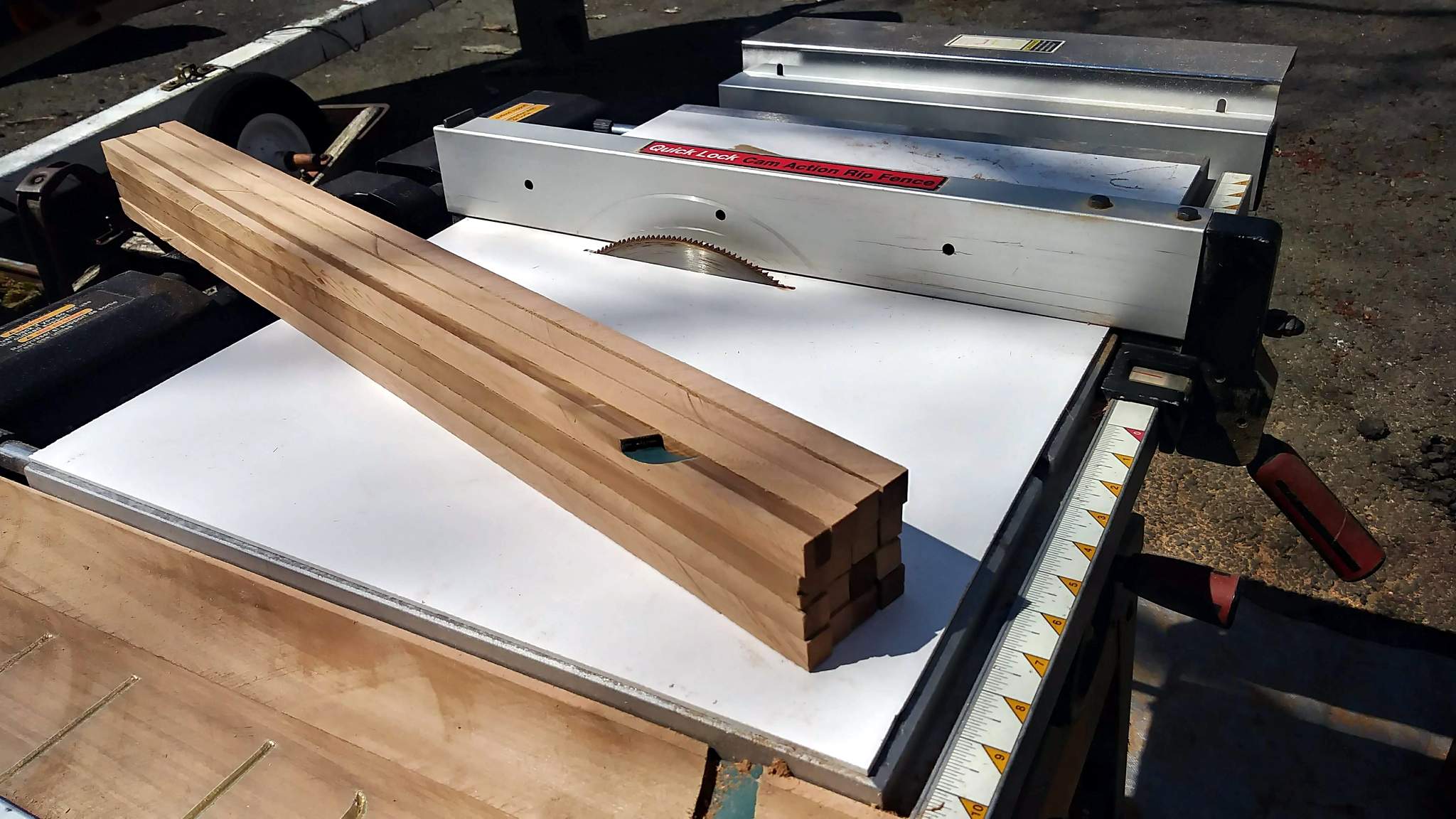
The day began by taking my table saw off the stand to replace the on/off switch, then putting it all back together. Once repaired, I dug out the remains of a carved wood sign that I had salvaged a few years back. It may be Redwood, or Cedar; not sure. Very tight grain…
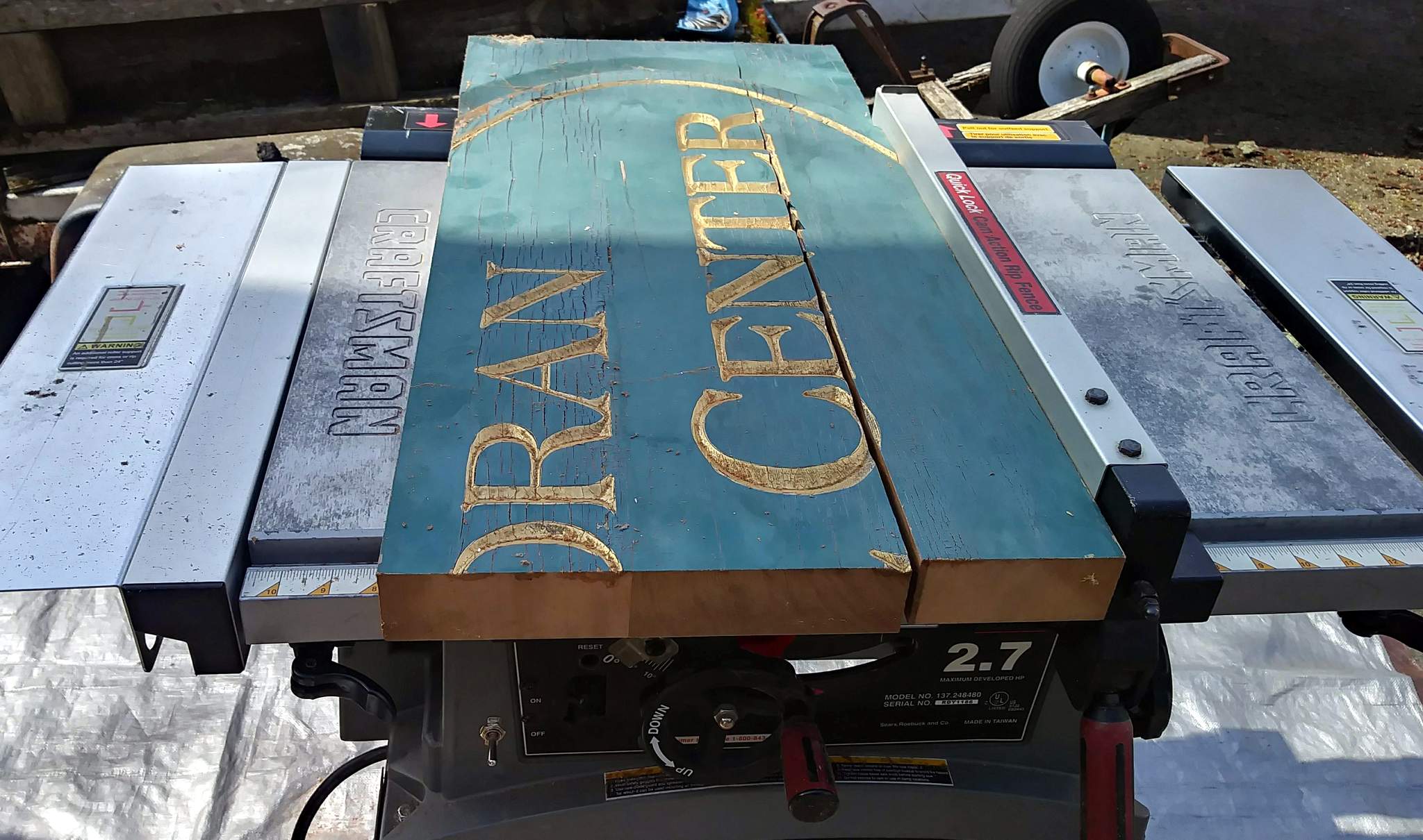
The first step in reclaiming this wood is to strip off the paint. I do this by slicing off about .375" leaving me with a nice veneer I can use elsewhere…
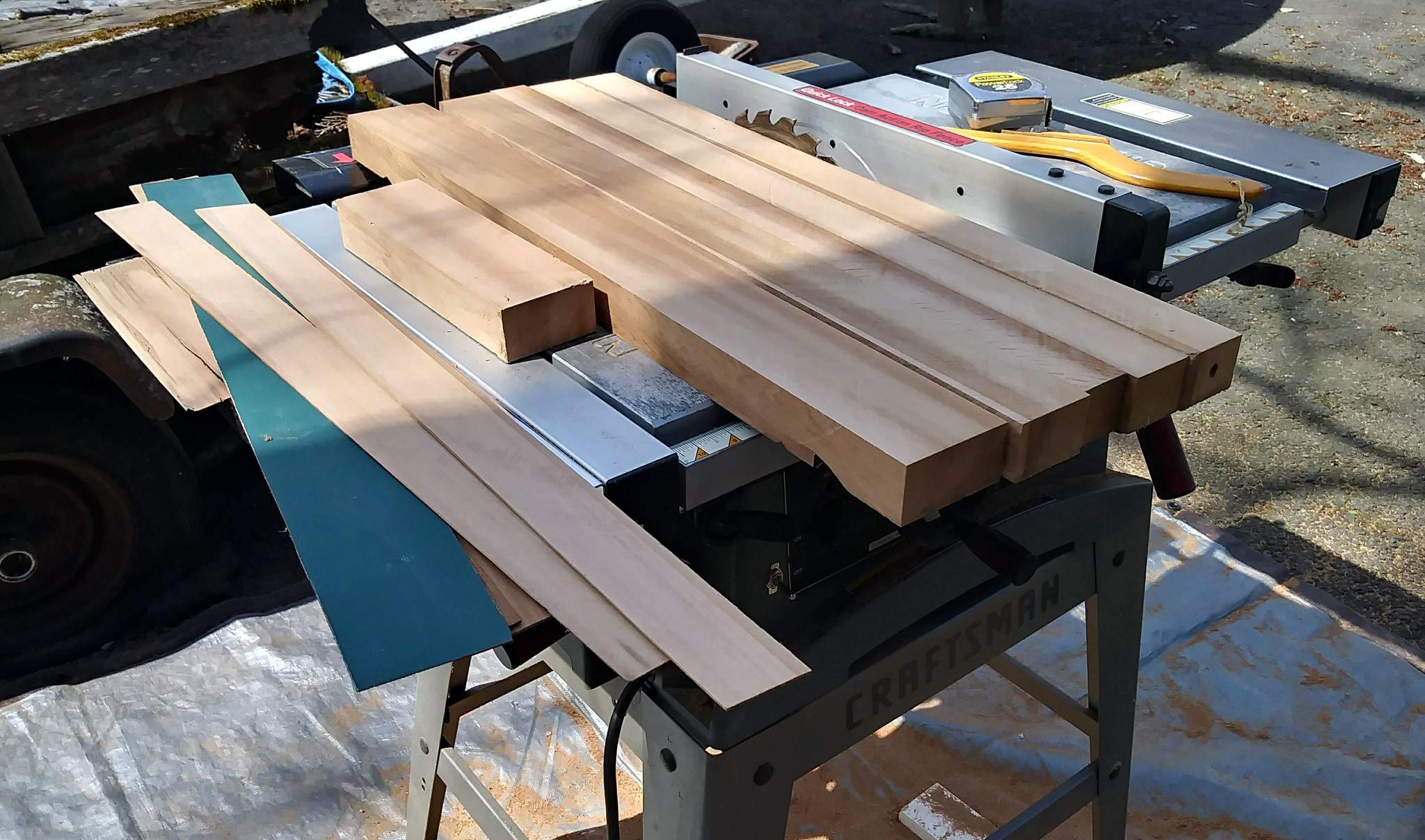
Flip it over and do it again, but because this is the carved side I only slice off just a tiny bit more than a kerf width; most ending up as sawdust. The deeper carving remains and will be cut away when the pieces are trimmed to final size…
For the next step I changed to a 200 tooth blade and made a zero clearance surface from a sheet of 3mm foamed PVC board. The lumber shown are the finish 12" x 12" timbers, about 47 scale feet long! You can see where the carving leaves a flaw in the timber…
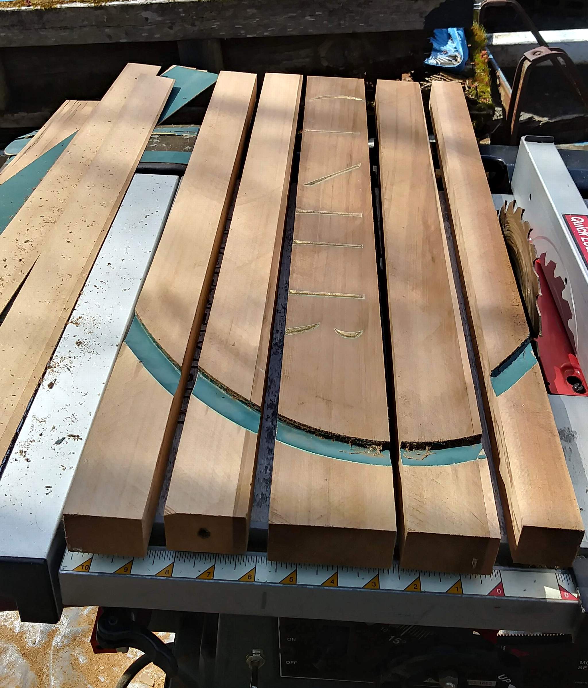
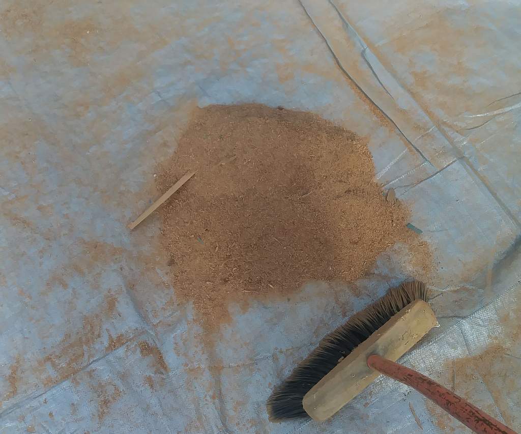
When finished, I had a larger pile of sawdust than timber…
I also milled up a bunch of what were supposed to be 2x6 for the deck, but In order to actually get them to cut consistently I up-sized them to a scale 2.5" x 6"…
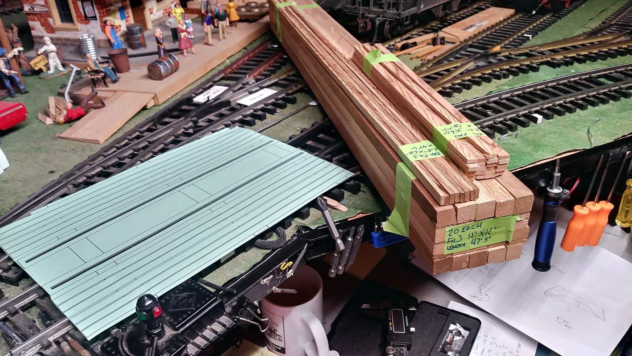
The next few days are supposed to be rainy here, so I’ll determine final dimensions to keep the track height the same then start cutting and thinking about an assembly jig.


