Large Scale Central

Full Control R/C in Bachmann C-19

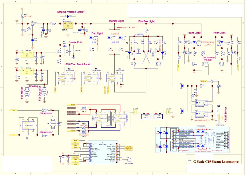
Hopefully Stan Ames is listening because these questions are primarily for him. I thought I would make a public post so that others may benefit from the information I hope to gain.

From what I have been able to figure out by various methods, leaving the DC board in the socket and connecting your R/C using the Battery terminals provided will result in operation similar to using a trail car. In other words, headlights and effects will be present only when the locomotive is moving. Unless the 6V Input terminals provide power for lights and effects. If the Headlamp is powered from the 6V input; is it on only running forward?

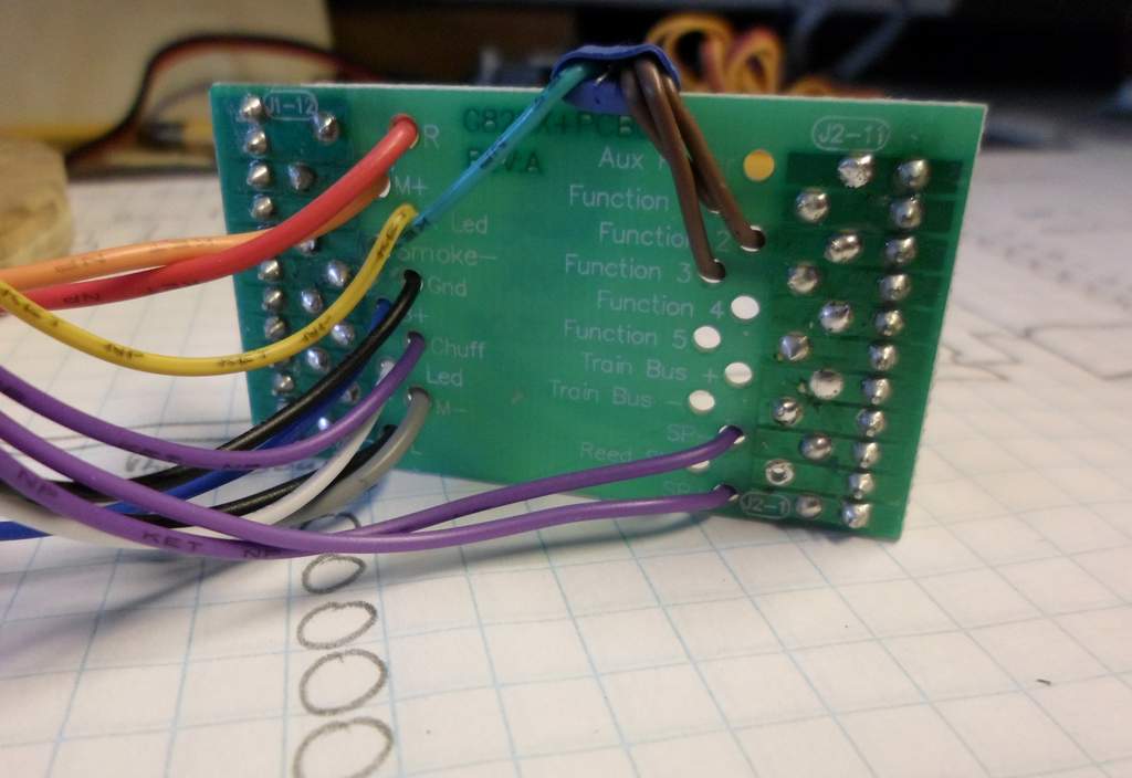
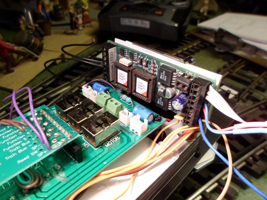
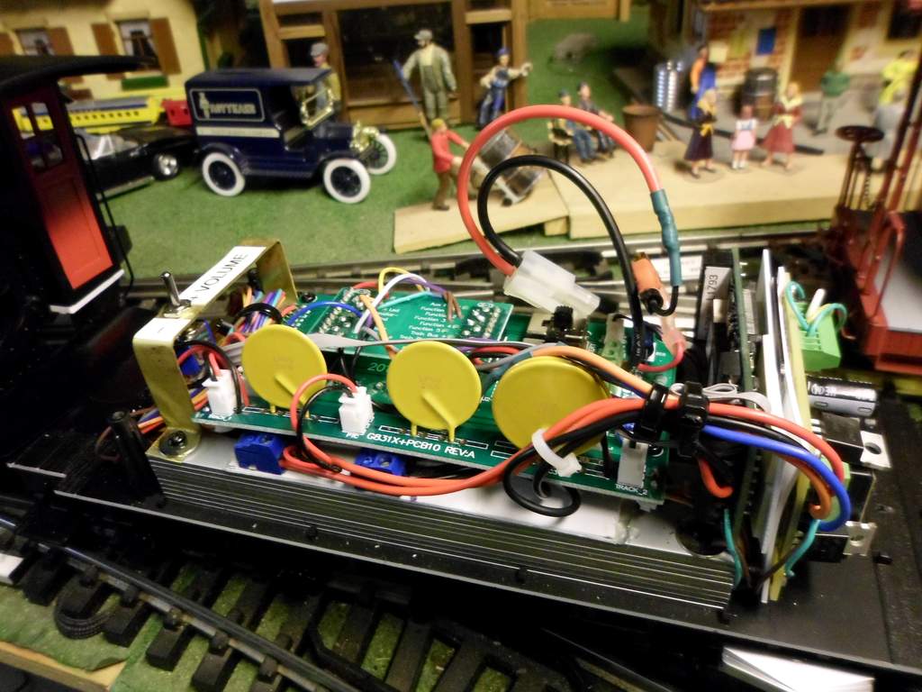
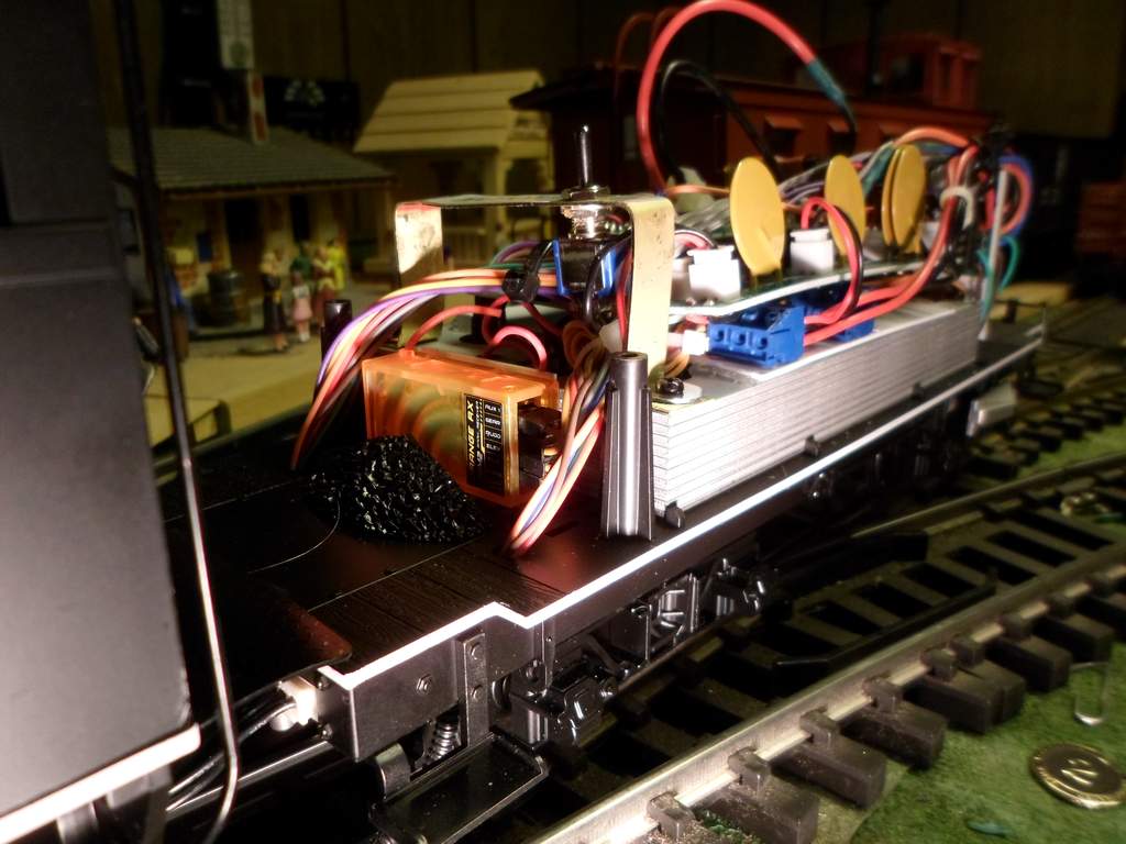
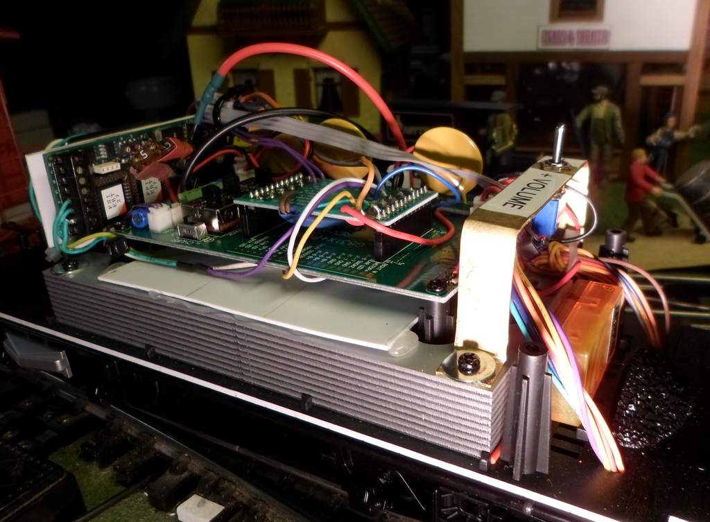
But I digress… Since I want complete control of lights and functions (like firebox & markers) I planned on removing the DC socket adapter board and using the pigtail adapter board to make my connections without soldering to the factory board. I did notice that when feeding the locomotive via the socket, the NMRA/LS and TRACK/BATTERY switches do nothing. So far I have success getting the loco to move and partial success with the headlamp.

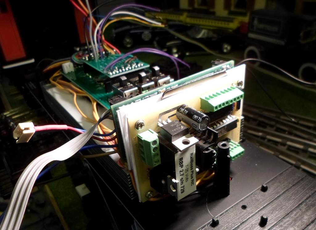
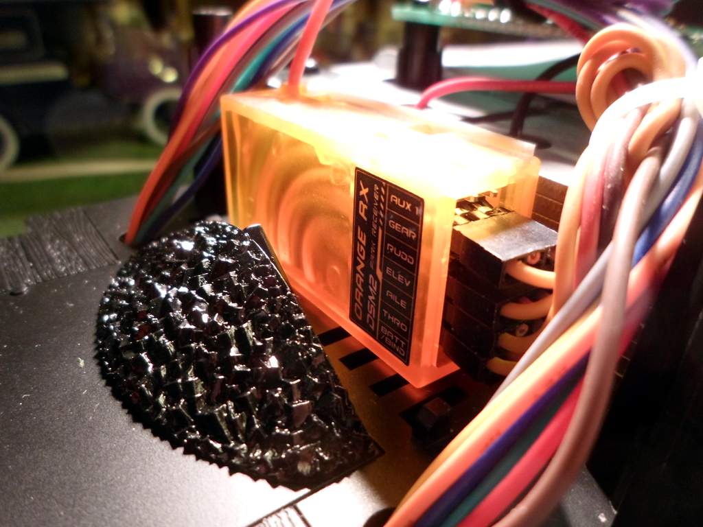
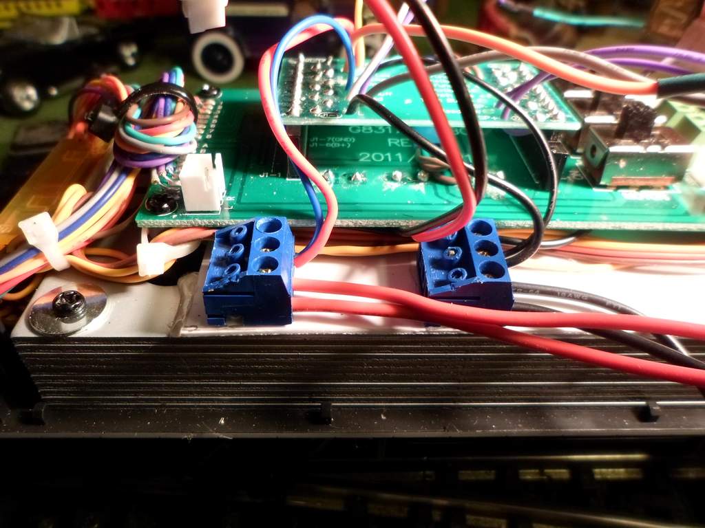
I am using an older model RailBoss Plus (later called Hobby) board and I may add Del’s trigger board for more functions. For motor control I am feeding J1-3 (Motor -) and J1-10 (Motor +) from the RailBoss Motor Out terminals. This successfully controls locomotive movement in both directions and, as expected, the loco moves with no lights or effects on.

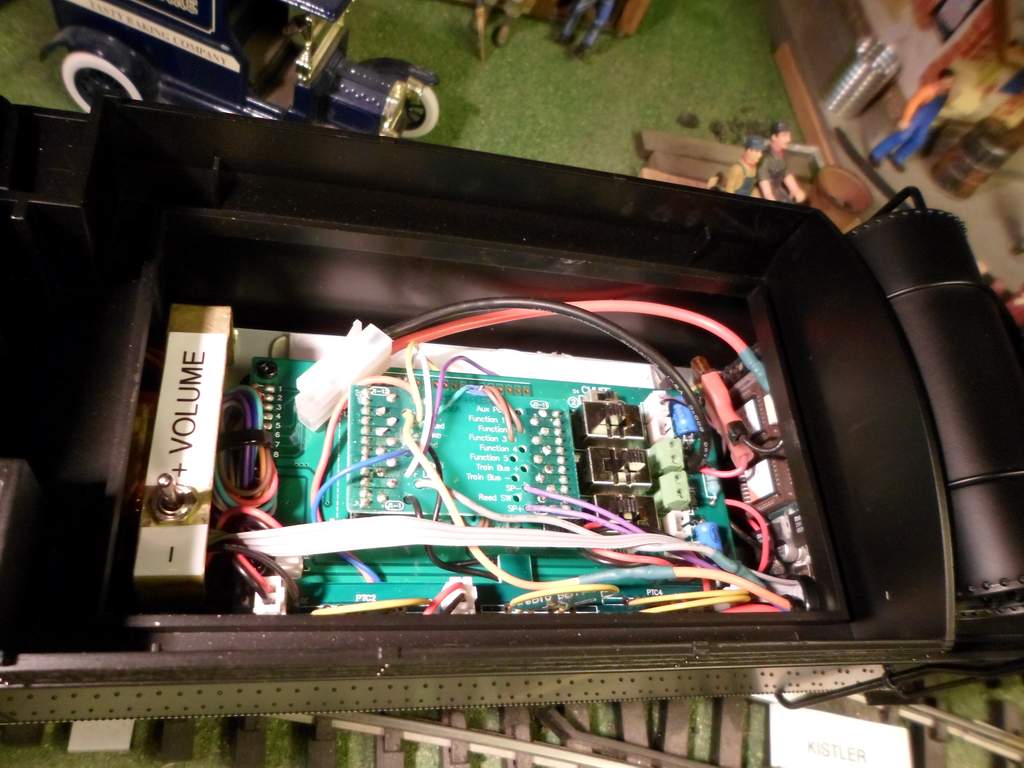
My next task is to get the headlamp functioning as it is used as feedback for programming the RailBoss. The RailBoss includes an LED driver circuit which provides a positive voltage current source and switches the ground for on/off control. Optionally, a positive battery voltage is available for use with lamps. I was encouraged when I saw in the socket pin assignments that the headlight connections were ground. So, as a test I connected J1-4 (Front Headlight Ground) to the Front LED ground connection on the Railboss. In order to function, the headlamp must get its current from somewhere. Assuming that J1-6 (Decoder Positive Output) would be that place, I connected it to the RailBoss LED current source. That alone didn’t light the headlight, so I connected J1-7 (Decoder Ground) to a ground output on the Railboss. With these 3 connections I got the headlight to light, but it is only bright when first switched on, then immediately goes dim.

So, folks who know, what is the proper way to feed the headlight? If there is already an LED drive somewhere in the locomotive circuitry, Should I feed it with the Railboss lamp circuit rater than the LED driver?

Where does the Headlamp (and other functions) get their positive voltage from?

What is the Train Buss (J2-4 and J2-5) for? I tried J2-4 as the plus voltage source, but no headlight at all. I did not try with J2-5 grounded.

1 Like

Hi John.

What you need is one of these:

They take either battery power or track power and provide filtered, rectified DC for any brand of R/C.

They also take the RailBoss lighting outputs to control the on board Front & Rear lights.

Go here to read up on what they do.

Thanks Tony. I’m sure that your board would simplify the job, but I’m a electronics tinkerer and really want to figure it out myself, plus I want to use a trigger board to turn the class lights and cab light on and off.

I’ll get there, just need to figure some stuff out without letting out any of the magic smoke.

Pins J1-6 and J1-7 carry battery voltage forward to the locomotive for lights, the chuff sensors, etc. I know the Revolution does not pass battery voltage through the board to these pins, so if you’re using the Revolution, you’ll have to jumper that yourself. The “porcupine” board, which I think is the one you’re using, would not, either. Look for the wires leading to those pins, and hook them to the battery + and - input. I forget off the top of my head which pin is + and which is -.

The headlight is controlled from the electronics in the locomotive itself. Unlike the K-27 where the headlight has a direct connection in the tender, the C-19 does not. On mine, it takes its power from the V+ and V-. There’s no way (that I could find) to independently control the headlight from the board in the tender without a re-wire.

Later,

K

Thanks Kevin.

I had a feeling that on-board lighting electronics were getting in the way; especially after I read that the front light dims in reverse. OK - Porcupine Board - good name for it. That is what I am using to isolate lights and functions for direct control. Once I get it working breadboard style I’ll remove all the wires I don’t need and solder new longer leads to the pins I use.

I also found some pretty good information on the Phoenix site that changes my approach on battery connection. I was hung up on the old-school method of connecting the battery directly to my ESC. My next experiments tonight will be connecting the battery to the provided screw terminals then powering my ESC from J1-1/2 and J1-12/13. This will return the function of both the track/battery and NMRA/LS switches and allow the ESC to get power from the rails or the battery. Rail power might come in handy for short moves indoors.

Once I do that, I have a feeling that the rest will begin to fall into place. Little bits of information are all over the place on the interwebs. Getting it all together inside my head is the challenge.

Daktah John said:

Thanks Kevin.

I had a feeling that on-board lighting electronics were getting in the way; especially after I read that the front light dims in reverse. OK - Porcupine Board - good name for it. That is what I am using to isolate lights and functions for direct control. Once I get it working breadboard style I’ll remove all the wires I don’t need and solder new longer leads to the pins I use.

I also found some pretty good information on the Phoenix site that changes my approach on battery connection. I was hung up on the old-school method of connecting the battery directly to my ESC. My next experiments tonight will be connecting the battery to the provided screw terminals then powering my ESC from J1-1/2 and J1-12/13. This will return the function of both the track/battery and NMRA/LS switches and allow the ESC to get power from the rails or the battery. Rail power might come in handy for short moves indoors.

Once I do that, I have a feeling that the rest will begin to fall into place. Little bits of information are all over the place on the interwebs. Getting it all together inside my head is the challenge.

John

Perhaps the attached C-19 circuit diagram will help. I also do not care to have the front headlight automatically dimmed when the rear headlight is on.

If you look at the circuit diagram this feature is achieved with the connection between Q1 and Q5. On the main tender board this trace is underneath on the front firemans side and easily cut.

Many RC systems simply plug into the socket for an easy installation.

Hope that helps

Stan

Thank you Stan, that will be a huge help. I will PM you my email address, could you perhaps send me that in better resolution?

I see that you uploaded a high resolution JPG, LSC is just shrinking it. I will download and save for future reference. I wonder why Bachmann does not publish this.

It’s unbelievably simple once you see how everything is wired. I was getting hung up on all those standard DCC pins that are not being implemented in this loco like Train Bus and Reed Switch input. Very little chance of loosing any magic smoke now.

Good news! Thanks to Stan sharing that most excellent schematic, I now have fully functional R/C and sound bread boarded and road testing without the tender shell. Now I am debating a permanent battery set up, or changeable pack. I have a full set (4) of new solder tab LiIon batteries and several protection PCBs in stock. I guess it’s going to come down to how everything fits.

Next up is function testing. Reading up on the RC trigger board I have; it should work fine to control the Class Lights. I’m using and old Phoenix Big Sound '97 because it was available with EBT Steam sounds in it. I might pull apart my original 1:29 Trail car (Cheesy Sound) some day and then upgrade the sound to 2K2 to get some more functions. That will wait until after Ken’s.

I really like the way Don “Doc” Watson laid his out. Fabricating the brackets looks easy for me. I will probably use Aluminum rather than brass because I have it on-hand - just not sure it will be strong enough. I have .040 and .063 that will bend in the brake at work. I also have .080 but it cracks when bent at room temperature.

Running out of time to get this buttoned up for a debut at Ken’s. I need to build a carrier too. No way I’m messing with those plugs more than I have to.

Here are the Install photos & details. My goal was to get full control of all functions without any modifications to the stock electronics, including soldering to the tender board. Soldering to the “Porcupine Board” is OK.

First, I enclosed the stock speaker by closing up the holes in the weight with styrene and hot glue. I then covered the top with a sheet of styrene trimmed to fit around the magnet and sealed with hot glue. By using hot glue I get a good seal and it is reversible with a heat gun. Here it is all buttoned up before putting the board back on…

Next up was cleaning up the Porcupine Board. I removed leads for all functions and lines that aren’t used in the C-19 then bundled up the ones I’m not using in Rev 1 with heat shrink to tuck under the board…

I borrowed a few ideas from Doc Watson’s install including removing the fan and sandwiching the fan bracket with my Rail Boss Plus board and a Phoenix Big Sound 97…

Eventually I will upgrade the sound board by swapping it out with a 2K2 that’s in Cheesy sound at the moment. This '97 board has EBT steam sounds in it with toggled bell and manual whistle…

I swear Bachmann must have measured these exact components. I placed my Orange brand receiver in font of the weight. The tender shell just fits in front of it and around the components on the RailBoss in the back…

Because I did not want to solder on the tender board pads, leaving the unit 100% stock (for now), I added a couple of power buss connectors. These have pins shorted together so all three screws are the same terminal. Having each component fed separately comes in real handy when troubleshooting…

I tried to get away without that little add-on board with the PTC components, but the two in the center are still needed to complete the battery source circuit so I put it back. It bows a little going over the wires. I also borrowed the switch bracket idea from Doc. I only need volume as I am using the Track/Battery switch as on/off with trucks disconnected…

Ready to put the shell back on…

And from the other side…

Tender shell fits on easily…

I opted to go with a removable battery pack. I didn’t build Doc’s battery shelf; I just lay it in top of the board.

Next up; lettering. I took measurements tonight. Might get some design time at the computer tomorrow.

Looks great, but I’m confused about the Orange receiver. What in that mass of electronics needs a servo feed? And where are the servos?

I think that is the wireless radio for the Rail Boss control system.

Greg

Yes, Greg has it correct. The earlier RailBoss systems and some of Tony’s RCS Systems use an external receiver and an aircraft style radio. I use the same two-stick radio with servos on my live steam Shay.

There are all sorts of tricky things you can do with Digital Proportional 2.4 GHz R/C.

Including controlling Kadee servo uncouplers direct from the Rx without any other parts.

DJ. If you plug the Kadee servos into Ch # 5 or Ch # 6 you can control them with a switch on the Tx.

Thanks Tony. I don’t have a want for remote uncoupling, but I’m sure I could come up with other ideas. Del’s later systems uses Ch 5 to select between two Locos which I use often. I have a DX5e now. Been watching your hand pieces develop for several years with interest. Some day (http://www.largescalecentral.com/externals/tinymce/plugins/emoticons/img/smiley-money-mouth.gif)

Bringing this old thread back for an update. Tonight I opened up the tender to remove the Phoenix Big Sound 97 board in preparation for installing a Phoenix 2K2 removed from the decommissioned Cheesy Sound Car. While it’s open I’m tempted to make a few more changes now that I’ve had some experience with the loco and am sure it is here to stay.

First the tender weight…

Does this huge amount of weight serve any purpose other than enhancing rail contact for power pick up? I can see having a little added weight for tracking, but this is a lot to pull up my grades. I’m tempted to remove it and replace with a lead at half or less of the weight and volume. If I do that I can fix my not so air-tight speaker enclosure to hopefully improve the sound at higher volumes.

Next is electronics. I need to completely isolate the track pick ups. I thought I did that when I did not connect the Track One and Track Two plugs to the PTC board.

I failed to realize that the locomotive wheels also have power pick up feeding to the tender. Isolation is needed as I now have 12V lighting power in my track and when I try and use the Batt/Track switch as the on/off it wants to move on the lighting power. Sure, I could add an on/off switch and leave it in Battery, but why bother. I had originally planned to not use the add-on PTC board, but found that without further mods it was required even on battery power. I now have the time to look at the circuit diagrams more closely and eliminate it and the track power connections all together.

Opinions on the weight are welcome.

The K-27 also had a whole lot of weight in the tender. With a battery and a speaker installed, I didn’t see any need for all that weight in the tender of either one. Besides, I needed the room to fit in a battery and all those plates just took up bunch of space that could be used for other electronics. Both of those engines are heavy enough without all that weight in the tender.

I used some of those plates in the railtruck to give it a bit more weight. How the drive train will handle it remains to be seen…(https://www.largescalecentral.com/externals/tinymce/plugins/emoticons/img/smiley-wink.gif)

Yep! I took out the plates and weighed them. Just under 1 pound. With them, and the stock boards removed, I just can fit a really nice speaker in a bass-reflex enclosure that I salvaged from a freind’s sound bar that died. I have yet to audition the speaker since it was midnight when I finally got done taking everything out of the tender. I will try and do that tonight and if it sounds as good as I think it will, the decision will be made.

EDIT to add: Since the trucks and frame are metal, the tender frame is pretty hefty without the weight. I don’t think it will be missed. Theoretically removing it adds 1 more pound of pulling power.

Spent several hours last night identifying all the wires between loco and tender. Without the drawing that Stan posted that may have been impossible since several lead to circuits on the tender board and can’t be traced with a continuity test. My test of the sound bar speaker made the decision. Stock electronics are coming out. I need to come up with a headlight circuit since the parts that allow switching it via ground are on the tended board. Will require some breadboard work, but I think I can reach my original goal with a little work.

Once I have it all figured out I will post all the details.

Sounds interesting Jon, after installing a Deltang R/C and Phoenix sound system in my K-27, while retaining the stock boards, I found it was more work than two wires to motor and two wires to the headlight.

I have got two more socket equipt Bachmanns to convert with limited bunker space (Climax & Forney), might have to rewire…

Where is your battery pack located?

Jon,

I never documented it but I do remember adding a 5volt power source to power leds and chuff sensors after I removed most electronics. I only have one of the two connectors between tender and loco in place. went from 14-15 wires to seven. did not power the smoke generator but did remove it.