Nice wood working. How do you shape it like that? (get it rounded so even on both sides)
slow and light on a belt sander to get the rough shape. But, it still needs to be hand sanded to final shape.And guide lines drawn wherever possible help
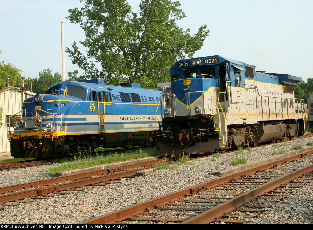
Somebody said something about it being the ugliest locomotive ever…so it must be this beastie here 
Ralph
(http://freightsheds.largescalecentral.com/users/cabby/_forumfiles/BO017.jpg)
That be the one gents. Thanks for the pic Ralph
They must have removed the HEP cables and ditch lights on that unit.
David Russell said:
They must have removed the HEP cables and ditch lights on that unit.
I thank to old to have them.
Nice work Dave
Richard
Thank you Richard.
yes Dave
those are add on for todays standers did not come with them. and this is 1977 http://rrpicturearchives.net/showPicture.aspx?id=2478243 and 1980 http://rrpicturearchives.net/showPicture.aspx?id=3430447
Richard
Love the D&H colors
Dick
It seems the BL2s mandate a love/hate response. There doesn’t seem to be many on the fence type opinions where they are concerned. Personally I have always liked the stand alone shape.Yes, as most have said, they’re an ugly beast. But, I like them.
Research has shown some of the flaws in the design from an operational standpoint, but I do think there were practical reasons for the design.
I have to say. it isn’t an attractive ole’ girl. But it’s definitely unique.
The project is coming along great. I wouldn’t have the patience to sand all those curves.
Very nice. I am one of those that like the BL-2, have some in N and O. Always wanted one in G for my pike. Looking forward to the build. Here is an active one in Elkins, WV
Jerry
(http://freightsheds.largescalecentral.com/users/naptowneng/_MG_4953.JPG)
I’m actually using her sister WM 81 for my build Jerry
82 would make a good example of where to put the ditch lights, Dave, if you’re gonna add them…
Just my opinion… 
I got the windows and doors cut in the main side pieces.

With those cut I lined up the pieces to get the marks I needed to cut the roof angles so I could cut the windshield frames and the rear window frames.

and notch the nose section for the frame pieces.


I also cut a recess in the roof block to blend the wood and plastic a bit better
The windshield frames


And the rear window frames

And to show I make my share of errors.

This is the first frame piece I was going to use (on the right), and the height mod I needed to make it work( on the left). I forgot to allow for the track I cut into the nose on the first one.Also if you look close at the nose and roof, you’ll note an extra piece of wood glued on in the center. I oversanded the curves and had to adjust. 
A couple of questions for those with the knowledge:
On this build I will be putting hoses on the pilots,and a large cable maybe.
What I’d like to know comes from this pic

There are 5 hose connections on each side of the pilot.
- What are the 5 (10) hose connections for ?
please note them in order from 1-5 and tell me if they are duplicates on each side
-
Were they all connected when the loco was in use ? in use when MUed ?
-
There is a covered plug above the deck, was it for an MU cable and if not what is it for?
-
If the above was MU was it connected along with the hoses or did it take the place of the hoses ?
Thank you for any help you can give.
No, it won’t make or break the build, but curiosity has set in and I like to know what I’m doing.
Dave Marconi said:
A couple of questions for those with the knowledge
There are 5 hose connections on each side of the pilot.
- What are the 5 (10) hose connections for ?
please note them in order from 1-5 and tell me if they are duplicates on each side
Were they all connected when the loco was in use ? in use when MUed ?
There is a covered plug above the deck, was it for an MU cable and if not what is it for?
If the above was MU was it connected along with the hoses os did it take the place of the hoses ?
Thank you for any help you can give.
No, it won’t make or break the build, but curiosity has set in and I like to know what I’m doing.
- Facing the cab, the small hoses are the following from inside to outside; Main Res line (connects all the locomotives in to one giant air tank), Actuating line (releases/applies the locomotive brakes when the engineer makes a set on the train line), Independent Line (applies/releases just the locomotive brake through the use of the independent). The next two are most likely the following; sand (air for controlling the flow of sand for the sanders) and whistle lines (not 100% sure on this, but it’s possible).
These hoses are repeated in duplicate on the right and left side of the cab, with the Main Res. line being the first small air hose after the main train line.The trainline hose will always be thicker than the MAI hoses. The MAI hoses are slightly smaller. The Main Res. line glad hand is open to the right. The AI lines are open to the left. This prevents the Main Res. line from getting laced up with the AI lines. The angle cocks on the MAI line are opposite the trainline angle cock. The train line angle cock is open when the angle cock is parallel to the train line, the MAI angle cocks are closed when parallel to their respective lines.
The MU connection is the electrical connection between locomotives. On modern locomotives its a 27 pin connection (controls sand, and bell/whistle electronically, thus those two air lines are no longer needed).
-
Yes all the air lines and MU lines must be connected for multiple locomotives to work together. The MAI lines must be connected correctly in order for the air to work correctly. If backwards you can apply the independent when you think your actuating the independent. This is the function of the locomotive air brake test, it ensures that the air lines are connected correctly, and the MU hose is as well. (Edit: Only one side of the MAI hoses need to be connected between locomotives for them to operate correctly. It’s common practice to lace up both sides to ensure steady, blockage free operation)
-
That covered plug is covering the MU connection.
-
The MAI lines work on air pressure to control the brakes. The MU hose controls the electronic brains of the locomotive.
Thank you for this lesson in locomotives Craig. really appreciated and saved