Large Scale Central

REVO II Speed Curve

In the “Assign Functions” menu of the Main Setup, is letter m. SPEED CURVE. I can’t find any mention of it in the printed documentation, no do I find it on their website. A web search is fruitless, also.

Do any of our electronic wizards know what it’s purpose is?

I don’t know Steve and we heard you the first time …(https://www.largescalecentral.com/externals/tinymce/plugins/emoticons/img/smiley-wink.gif)

Most DCC decoders have alternate speed curves, basically voltage vs. speed setting:

crappy picture, but:

The Revolution system often used “DCC buzzwords” but implemented a different idea, in the fervent hope that it would replace DCC (just like the Kuppler!)

The speed curve in the Revolution is an “offset” to the voltages applied to the motor across all speed steps, and it is often used to match loco speeds in a consist.

I cannot find it in the manual, but I did figure it out once by testing.

Greg

Explained Here https://www.aandhmodels.co.uk/speed-curves-1640-c.asp

Howto https://dccwiki.com/Speed_Table

To reiterate: Dan, that information is true for DCC, not the Revo… the start speed, speed steps, and speed curve all work DIFFERENTLY… as I said, the speed curve is basically an offset speed added across the existing speed “curve”… it introduces what is basically a constant

I made a point of the fact that the Revolution system often uses DCC terms for functions that are not the same.

(I own 3 DCC systems, and every model of Revolution 2.4 made (except the non-linear base station). I was also in the beta test group,

And I still have my correspondence with Lewis when the Revolution had a thumbwheel and ran at 900 MHz… I liked that throttle design better too)

Greg

I can’t find any documentation on it, either, but I vaguely remember seeing something when it was first implemented in the firmware.

I’m borrowing this graphic from a DCC illustration, but since it uses percentages, it works okay-ish to illustrate what’s going on with the Revolution. Pay no attention to the numbers along the horizontal or vertical scales, just the shapes of the lines.

In any case, with the Revolution, you set your start and top speed as a percentage of the total voltage. That would draw a straight line between those two points. The voltage change from step to step would be the same across the entire range. That would be the solid line. With the speed curve adjustment on the Revolution, you adjust it up (+#) or down (-#). If you adjust it up, it changes the line to what is shown by the green dotted line, to where the changes in voltage between steps on the first half of the curve is greater than the changes between steps on the second half. If you adjust it down, the voltage change between speed steps is less on the first half of the curve versus the second half.

Ideally, you’d adjust this so the changes in actual speed of the loco from step to step would be the same across the entire speed range (or as close to it as you can get).

Hope this helps a bit.

Later,

K

I found a post from 2012 that indicates the original firmware had a linear speed curve and it was just a variable offset.

Then there was a firmware upgrade, which apparently had nonlinear speed curves, but unfortunately references a document on the Aristo site that is no longer there.

http://forums.mylargescale.com/38-traditional-power/24454-crest-2-4-ghz-train-revolution.html

I cannot find a manual that references this… and apparently the link to the manual is long gone:

http://aristocraftforum.com/NewDocs/revolution/Revolution_Cre57000-3.doc

Greg

Thanks, all.

So, if i understand this right, if i adjust the curve down, say, give it a -1 or -2, I’ll get finer control at switching speeds, than at mainline speeds. Is that about it?

Remember, im not to be trusted with a light switch.

Theoretically, yes. The shallower the curve, the less the voltage changes between speed steps, which means you would have finer control at switching speeds. How far down you need to adjust the curve to where it becomes noticeable will depend on the locomotive. After you pass that mid point, each progressive increase in the throttle will result in a much greater change in voltage, and the loco will move quicker, faster. (If that makes sense.)

Later,

K

So, giving the curve a -1 rating would give me finer slow speed control than a -3, or would it be the reverse? How much of a numerical entry would be required to be noticible?

Steve…Now you are asking about your own learning curve ? I’m upset that you haven’t told me to shut up yet as my permit to carry concealed feelings is due for renewal. Greg and Kevin will hash/work this out for you.

Steve Featherkile said:

So, if i understand this right, if i adjust the curve down, say, give it a -1 or -2, I’ll get finer control at switching speeds, than at mainline speeds. Is that about it?

Remember, im not to be trusted with a light switch.

Hi Steve,

I couldn’t find anything either about the (M) “Speed Curve”, all of mine are set to “0”. But what I do know is, if you want finer low speed control, for switching, set the (L) “Speed Steps” to a lower number.

1 will change your speed by .1% for each press of a speed button

2 will change your speed by .5% for each press of a speed button

3 will change your speed by 1.0% for each press of a speed button

4 will change your speed by 2.5% for each press of a speed button

And 5 will change your speed by 5% for each press of a speed button

I don’t MU my engines but if you do, I would think you’d want all your engines in a consist to have the same “Speed Steps” settings. Maybe that’s set automatically when you set up multi-unit consists? I’ve never MUed a couple of my locos.

Adam

Steve Featherkile said:

So, giving the curve a -1 rating would give me finer slow speed control than a -3, or would it be the reverse? How much of a numerical entry would be required to be noticible?

A -3 would give you finer control on the first half of the curve than a -1 would. A -5 would be even finer control. (I don’t have my transmitter with me at the moment, so I don’t know how far you can adjust it.) The more the departure from 0 (linear), the greater the “bow” of the curve.

Here’s a better illustration… Again, borrowed from a DCC manual, so don’t worry about the numbers. Just look at the curves themselves.

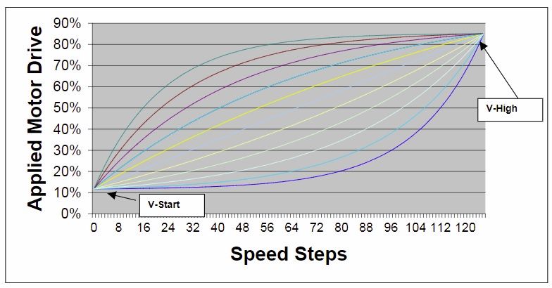
The light blue line in the middle of all that stuff is the linear (unmodified) speed curve. (Value of 0) As you increase the speed curve (+1, +2, +3, etc.) the curve bows increasingly upwards, so yellow, blue, magenta, rust, cyan lines. With the curve bowing this way, the speed increases quickly to start, then the increases get smaller and smaller with each speed step. Negative values (-1, -2, -3, etc.) would bow the curve increasingly downward, so light yellow, light green, lilac, light blue, and purple. With the curve bowing in this direction, the greater the departure from straight, the slower the speed would increase with each press of the button to start, then it would start shooting up towards the upper end of the throttle.

Now, what I don’t know is whether the Revolution does a smooth curve like this, or if it’s two straight lines from the start to mid point to end. My money would be on the latter.

To answer your question of how far do you need to go before you see a difference, I think that would depend on the locomotive. Motor speed to voltage isn’t necessarily a straight linear relationship. That means a motor doesn’t necessarily turn twice as fast at 10 volts as it does at 5 volts. You’ll have to play with it to get it to your liking.

Later,

K

Hi, Adam, I discovered the speed steps yesterday. Refer to my comment above about not being trusted with a light switch. (https://largescalecentral.com/externals/tinymce/plugins/emoticons/img/smiley-tongue-out.gif)I set mine to 2, as an experiment, and because I didn’t want to wait all day to get up to track speed.

I have my two GN SD 45s mu’d together, and found that both have to have the same "speed steps indicated, for the mu to indicate the value you want, otherwise, the mu value will default to “3.”

So, the speed curve might have value if i want to keep the upper range of the speed steps, and yet have the finer slow speed control. Time to experiment.

Steve, for what you want, play with the speed steps first… the higher steps will give you less speed per “push”

Then experiment with the curves, I seem to remember the minus will give you less speed per step in the lower voltages…

I’m going to contact Navin and see if I can get at least a graph of the curves. I agree that for what you want the curves should do what you want.

Greg

Thanks, Kevin. As I told Adam, it’s time to experiment. Film at eleven. (https://largescalecentral.com/externals/tinymce/plugins/emoticons/img/smiley-laughing.gif)

Thanks, Greg. I’ll be interested in what Navin says.

Tom, can you save it as a .pdf and upload it to your freight shed? Then you can post a link and folks can download it.

Later,

K

Here is the Aristo document Revolution_Cre57000-3.pdf

Thanks, Joe! The speed curves are explained on the bottom of page 2.

Later,

K