Hey Jerry,
with od i meant 120 deg of from the Crank. (3x120=360)
think global Pius
Hey Jerry,
with od i meant 120 deg of from the Crank. (3x120=360)
think global Pius
PJ:
Good observation about the location of the counterweights! I was so busy looking at the ‘crank’ on the center of the axle that I didn’t notice where the counterweights were located. Just went back to look. I should have also picked that up in the first place.
So now, we have two points that show that wheelset is from a three cylinder engine.
Can I ask, where was the picture taken? Assuming the wheels are from a German 2-10-0 as HJ wrote, it must be in Europe??
My apologies for taking this far OT.
Happy RRing,
Jerry
Jerry Bowers said:
PJ: Good observation about the location of the counterweights! I was so busy looking at the ‘crank’ on the center of the axle that I didn’t notice where the counterweights were located. If i remember right, we got all kind of information, but not the answer to your question. Just went back to look. I should have also picked that up in the first place. So now, we have two points that show that wheelset is from a three cylinder engine. Can I ask, where was the picture taken? Assuming the wheels are from a German 2-10-0 as HJ wrote, it must be in Europe?? My apologies for taking this far OT. Happy RRing, Jerry
Hey Jerry, I am surprised that the Canadian railroad does not use a different angle then 120deg, and if you look at the link you can see that all the information we got from Canada, is 1:1 present on that webpage. Some folks do know mechanics, others know how to trace a link on a Picture which is posted in this forum. Reminds me for a earlier discussion about radius and fillet. think global Pius you asked: Can i ask where the picture is taken? This axle is displayed on the German Railway station in Trier. By the way, if you move the Mouse on top of the picture, push right mouse switch, and select copy Image Location, then you can place (paste) link in Google search word Wiondow, so you can find the original location of some Pictures. here the link: http://images.google.com/imgres?imgurl=http://upload.wikimedia.org/wikipedia/commons/thumb/2/22/Trier_Bahnhof_Triebachse_Baureihe_44.jpg/800px-Trier_Bahnhof_Triebachse_Baureihe_44.jpg&imgrefurl=http://commons.wikimedia.org/wiki/Image:Trier_Bahnhof_Triebachse_Baureihe_44.jpg&h=600&w=800&sz=119&hl=en&start=12&tbnid=zCqaTmsMOxMHeM:&tbnh=107&tbnw=143&prev=/images%3Fq%3DBahnhof%2Btrier%26gbv%3D2%26hl%3Den%26client%3Dfirefox-a%26rls%3Dorg.mozilla:en-US:official%26sa%3DG
Looks like Google does not alow to copy paste link, but when you go to google and enter in search this, " Image Trier Bahnhof Triebachse Baureihe 44.jpg-Rosja " you will find the webpage with all the information.
Description Bahnhof de:Trier Triebachse de:DRG Baureihe 44
selbstfotografiert Mai 2004
GNU-FDL
Fotograf: Stefan Kühn
Source Originally from de.wikipedia; description page is/was here.
Date 2004-06-10 (original upload date)
Author Original uploader was Stefan Kühn at de.wikipedia
PJ said:
Jerry Bowers said:
PJ: Good observation about the location of the counterweights! I was so busy looking at the ‘crank’ on the center of the axle that I didn’t notice where the counterweights were located. Just went back to look. I should have also picked that up in the first place. So now, we have two points that show that wheelset is from a three cylinder engine. Can I ask, where was the picture taken? Assuming the wheels are from a German 2-10-0 as HJ wrote, it must be in Europe?? My apologies for taking this far OT. Happy RRing, JerryHey Jerry, I am surprised that the Canadian railroad does not use a different angle then 120deg, and if you look at the link you can see that all the information we got from Canada, is 1:1 present on that webpage. Some folks do know mechanics, others know how to trace a link on a Picture which is posted in this forum. Reminds me for a earlier discussion about radius and fillet. think global Pius you asked: Can i ask where the picture is taken? This axle is displayed on the German Railway station in Trier. By the way, if you move the Mouse on top of the picture, push right mouse switch, and select copy link, then you can place (paste) link in Google search word, so you can find the original location of some Pictures. here the link: http://images.google.com/imgres?imgurl=http://upload.wikimedia.org/wikipedia/commons/thumb/2/22/Trier_Bahnhof_Triebachse_Baureihe_44.jpg/800px-Trier_Bahnhof_Triebachse_Baureihe_44.jpg&imgrefurl=http://commons.wikimedia.org/wiki/Image:Trier_Bahnhof_Triebachse_Baureihe_44.jpg&h=600&w=800&sz=119&hl=en&start=12&tbnid=zCqaTmsMOxMHeM:&tbnh=107&tbnw=143&prev=/images%3Fq%3DBahnhof%2Btrier%26gbv%3D2%26hl%3Den%26client%3Dfirefox-a%26rls%3Dorg.mozilla:en-US:official%26sa%3DG
Pius, You are so funny! :lol: Let me put it this way: anyone who can’t see that it is a three cylinder engine because of the axle config, doesn’t just need glasses, but also needs to read a book or two on prototype steam engines. That the different cranks will be off-set by 120º is plain logic, any other “quartering” would certainly lead to interesting mechanical/centrifugal imbalances. But you knew all that, didn’t you?!? Hey, how’s this for a secret pointer: there’s an interesting book on Swiss steam written by Alfred Moser, it’s in German (that should help) the ISBN # is 3-7643-0742-0. I recommend it to anyone who hasn’t got a clue about steam in general and Swiss steam in particular, but has some basics in mechanical engineering. 

 It’s not always easy to find - I’ve had mine for more than 20 years, there has been a reprint since. You can then even tell us how that E3/3 with the pantograph actually worked. That is as interesting as a 3 cylinder superheated steamer from the DB. PS On that webpage: no need for me to look that up I have a nice handy book on all the German SG steamers, along with one on Diesels as well as electrics. Those are about 30 years old. Despite my main interest being Swiss electric engines I have close to ten books strictly on steam engines. The Internet is super handy, but I was interested in trains a long time prior to anyone even considering the Internet - that was invented by Al Gore, wasn’t it or was it Steve Jobs or was it Rube Goldberg?
Jerry Bowers said:
PJ: Good observation about the location of the counterweights! I was so busy looking at the ‘crank’ on the center of the axle that I didn’t notice where the counterweights were located. Just went back to look. I should have also picked that up in the first place. So now, we have two points that show that wheelset is from a three cylinder engine. Can I ask, where was the picture taken? Assuming the wheels are from a German 2-10-0 as HJ wrote, it must be in Europe?? My apologies for taking this far OT. Happy RRing, Jerry
Hey jerry, the other point is the single crank in the center of axle, and looking at the picture i guess you can see where the others would be located. think global pius
(http://upload.wikimedia.org/wikipedia/commons/b/bf/Triebwerk_BR44.jpg)
Pius,
You won’t believe this but the outside cylinders of the BR44 were simply connected to the driving wheels in the usual manner … errrrrr … I mean the cranks were offset by 120º instead of the customary 90º.
Jerry Bowers said:
PJ: Good observation about the location of the counterweights! I was so busy looking at the ‘crank’ on the center of the axle that I didn’t notice where the counterweights were located. Just went back to look. I should have also picked that up in the first place. So now, we have two points that show that wheelset is from a three cylinder engine. Can I ask, where was the picture taken? Assuming the wheels are from a German 2-10-0 as HJ wrote, it must be in Europe?? My apologies for taking this far OT. Happy RRing, Jerry
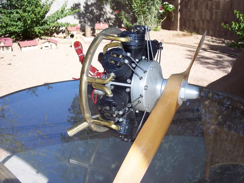
Hey Jerry, My girlfriends father used to say: I love a challenge of whits, but i refuse to fight an unarmed man. I like to modify that a bit: I love a challenge of whits, but i refuse to argue with copy past people. Since i have seen where such arguments lead (LGB Repair Time) i have no interest on such discussions. Rumor has that someone may thinks that i have no clue when talking about mechanics, others read books and know everything. Some folks know everything from hearing or again from reading it somewhere, in general i prefer the hands on version, and talking about real experience. Well, what are words if someone has nothing to backup what they claim, here just a few pictures of my mechanical projects. (just fun not work) Think global Pius My all time favorite scratch built motor, 70cc four stroke, radial, and yes it runs.
(http://i168.photobucket.com/albums/u175/Rigibahn/100_2487.jpg)
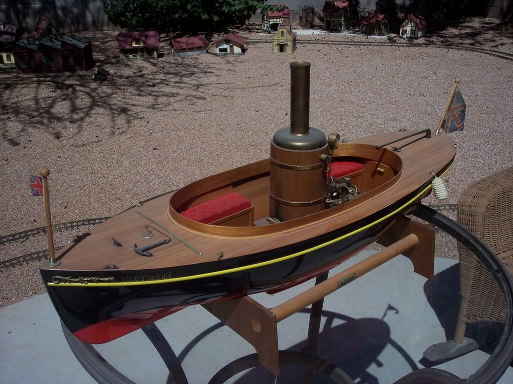
My scratch built boiler, sure the boat i made to, the engine is of shelf four cylinder Enya.
(http://i168.photobucket.com/albums/u175/Rigibahn/100_2491.jpg)
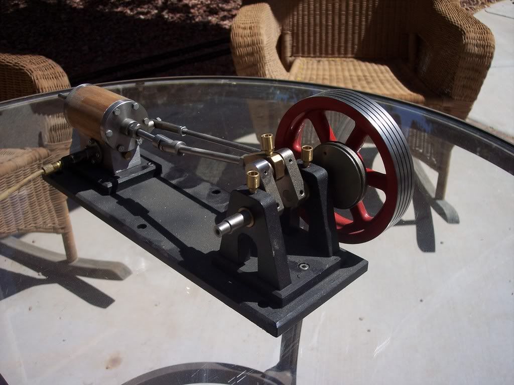
My scratch built steam engine, had some trouble with the valve, but now it runs fine.
(http://i168.photobucket.com/albums/u175/Rigibahn/100_2496.jpg)
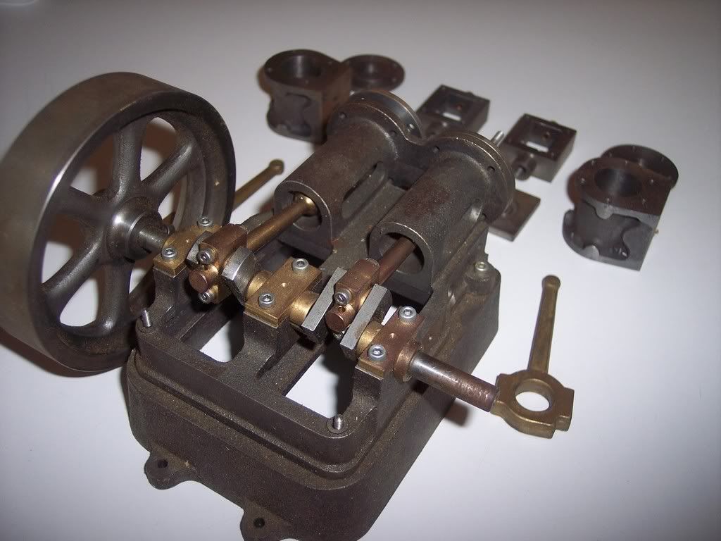
Project ongoing, 2Z steam engine, not finished.
(http://i168.photobucket.com/albums/u175/Rigibahn/KISS%20LOK/2-ZSteamEngine.jpg)
Upgrading my live steam with, real steam tower.
(http://i168.photobucket.com/albums/u175/Rigibahn/KISS%20LOK/Lok-Steam.jpg)
Pius,
If you fiddle with live steam, but don’t recognize a cranked axle when you see one … hey, who am I to say! For all I know it’s another hot day in Phoenix :lol:! OTOH I don’t need an engineering degree or hands on live steam experience to recognize that.
BTW when I used to interview applicants for service engineer jobs I would do the following: Chat with them for 10 minutes, then present them with a mechanical assembly drawing, the electrical/electronic schematics and the hydraulic schematic of a particular machine. Told them they have 30 minutes to study the material and I’d be back. When I got back I expected them to be able to tell me the basic functions of the machine in question and how one specific, basic routine would work.
Oh yes, some would call me a SOB, others would call me one tough SOB, but I would never ask anyone to do anything that I wasn’t able to do myself.
Well you know, I’m sure glad you did figure out that wonderful MTS control and changed to something slightly better. Those were the days, eh!??!
:lol: :lol:
PS On the copy/paste, when I do that I usually do it as a quote complete with source, OTOH as a rule I type well enough that I can re-type information from a book without glaring mistakes. It’s what I call “attention to details”.
Jerry Bowers said:
PJ: Good observation about the location of the counterweights! I was so busy looking at the ‘crank’ on the center of the axle that I didn’t notice where the counterweights were located. Just went back to look. I should have also picked that up in the first place. So now, we have two points that show that wheelset is from a three cylinder engine. Can I ask, where was the picture taken? Assuming the wheels are from a German 2-10-0 as HJ wrote, it must be in Europe?? My apologies for taking this far OT. Happy RRing, Jerry
Hi Jerry, What do you think how the axle (crank) of this engine might look. Some folks know right away that it might look similar to the first one posted, others know after the fact and argue and argue.
(http://webp1.mimas.ac.uk/~zzaascs/mrsoc/gallery/coll/3626-150.jpg)
(http://webp1.mimas.ac.uk/~zzaascs/mrsoc/gallery/coll/1757-beatrice150.jpg)
It is a good thing to know where to end a fruitless discussion, where to ignore something or someone, so that it does not end like other discussions I see in this forum, like (LGB repair Time) where the real subject is gone and any new posting is just to insult others, to be right regardless of price. think global Pius
PJ said:
Jerry Bowers said:
PJ: Good observation about the location of the counterweights! I was so busy looking at the ‘crank’ on the center of the axle that I didn’t notice where the counterweights were located. Just went back to look. I should have also picked that up in the first place. So now, we have two points that show that wheelset is from a three cylinder engine. Can I ask, where was the picture taken? Assuming the wheels are from a German 2-10-0 as HJ wrote, it must be in Europe?? My apologies for taking this far OT. Happy RRing, JerryHi Jerry, What do you think how the axle (crank) of this engine might look. Some folks know right away that it might look similar to the first one posted, others know after the fact and argue and argue.
(http://webp1.mimas.ac.uk/~zzaascs/mrsoc/gallery/coll/3626-150.jpg)
(http://webp1.mimas.ac.uk/~zzaascs/mrsoc/gallery/coll/1757-beatrice150.jpg)
Which one could it be? why did no one ever build a direct drive one cylinder steam engine?
(http://www.dlok.de/img_files/treibradsatz.jpg)
It is a good thing to know where to end a fruitless discussion, where to ignore something or someone, so that it does not end like other discussions I see in this forum, like (LGB repair Time) where the real subject is gone and any new posting is just to insult others, to be right regardless of price. think global Pius
PJ said:BUT
think global Pius
pay attention to the details, otherwise your world caves in. :lol:
BTW coming back to the original topic “Where to clean track”, I usually clean where and when it needs it. Having operated on many different layouts incorporating a wide variety of scales I couldn’t help but notice: those layouts which get used often, need the least cleaning. That is irrespective of how tarnished/oxidized the track looks.
As a matter of fact just for kicks I tried the kerosene treatment on some of the MicroEngineering Code55 weathered rail without polishing the railheads bare. Well, well, well, wouldn’t you know it, that worked like a charm, no sputtering, no stalling, no problem and the inside of the railhead must have had just as much “weathering” on it as the rest. And all this in HOn3 without any sliders or other such crude methods.
Would that be because the rail to wheel match-up is more proto or is it just because clean is clean and that’s all there’s to it.
Oh on a related topic i.e. getting the current across a gap. There used to be a Swiss machine tool mfg who had a bit of a problem supplying the current to el.mag. clutches - intermittently and with disastrous results - so yours truly applied a bit of technology that is used in the MRR field. Modified one machine, test ran for two months without a single failure, sent the mod/schematic/explanation etc. to the mfg. From there forward all those machines came with that modification.
Of course I’ve known for a long time that it isn’t necessarily what you once learned to get a diploma, it’s how well you retain what you’ve learned, build on that and how readily you can apply it to situations that are completely unrelated.
A typical instance would be running a DCC control system in a hot climate. Since that applies to the Okanagan Valley (it was 100+ºF the other day) I certainly planned to install all the PS and the central station in the cool garage. Why tempt Murphy if it stands to reason that normal ambient temperatures, along with the fans in the PS Mega-Housing, will keep things cool. That along with keeping the stabilized DCC at no more than 20V is prevention of “major grieve”.
PJ:
Your mechanical work shown in your pix is superb! I especially like both the radial engine and the steam launch!! Is the radial engine a kit or is it scratchbuilt?
PJ said:Of course you know that it would be somewhere between difficult and impossible to start a single cylinder engine if it got stopped at either 'top' dead center or 'bottom' dead center ). Small single cylinder engines that can be rotated by hand have been made, with some in common use on applications where they could be started, but I'm not aware of any single cylinder machines as big as a steam locomotive getting beyond the very early days. Of course someone here will now post an engineering solution to that problem, so nothing imaginable by man is totally impossible. ;) ;) ;)
why did no one ever build a direct drive one cylinder steam engine?
In the two photos of axles at the bottom of your post, the left hand picture with the single crank lobe in the center certainly belongs to a three cylinder engine. The right hand picture doesn’t appear to belong to either of the locomotives above that have no visible valve gear. In addition to the two crank lobes between the wheels, the right hand axle picture appears to show both side rod cranks and additional relatively light weight cranks on the outside of the wheels. I would assume these are for valve gear and none is visible on the locomotives shown above.
PJ said:I'm not certain what you mean by this comment, but I consider the discussion of interesting mechanical design, including details of the thinking and engineering that went into it to be fruitful, providing an interesting learning experience. That even applies to relatively arcane technical solutions that have come and gone. I'm in the contract systems design and engineering business, and one way I make engineering / design decisions is by looking at what went before. The combination of modern or emerging technologies coupled with the best of existing design while carefully avoiding past errors has proven to be a pretty successful formula for me.
It is a good thing to know where to end a fruitless discussion, where to ignore something or someone, so that it does not end like other discussions I see in this forum . . .
I certainly do agree that the back & forth name calling gets very tiring, but one can always just skip what we don’t want to read.
Happy RRing,
Jerry
Hi Jerry,
First i like to answer your question: I especially like both the radial engine and the steam launch!! Is the radial engine a kit or is it scratch built?
-The engine is scratch built, anything you see i machined, just the screws dowel pins, spark plugs, prop or ball bearings are of-shelf parts. I built 3 of them, one i sold to a collector, this radial is now displayed in a public place. One i have at home displayed, and the third one is still in parts, waiting for the right day to be a project for me and the boys, to teach my kids something new. While manufacturing all the parts, I went so far and produced my own piston rings. Since you are in to mechanics, i guess you can image what a challenge it is, for example to produce a piston ring that is spring loaded, but when placed in the cylinder it has to be perfectly round.
You wrote: Of course you know that it would be somewhere between difficult and impossible to start a single cylinder engine. of course someone here will now post an engineering solution to that problem, so nothing imaginable by man is totally impossible.
-One cylinder DIRECT LINK TO AXLE, will not work really, unless you push the engine to overcome OT, if the piston is in upper/lower dead point, you have a problem. There is a good reason why a two cylinder has a 90 deg offset, and not 180 deg (left Right side)
you wrote: In the two photos of axles at the bottom of your post, the left hand picture with the single crank lobe in the center certainly belongs to a three cylinder engine. The right hand picture doesn’t appear to belong to either of the locomotives above that have no visible valve gear.
You Wrote: I certainly do agree that the back & forth name calling gets very tiring, but one can always just skip what we don’t want to read.
-I absolutely agree with you, and like mentioned previously, i know when to end a discussion, when to ignore something or someone in particular. But then again, it is like in politics, as a member of a community, sometimes we have to speak up if things are out of line, just or always ignoring wrong doing is not right.
think global Pius
PJ said:
.........................But then again, it is like in politics, as a member of a community, sometimes we have to speak up if things are out of line, just or always ignoring wrong doing is not right.
think global Pius
Precisely the reason I reply when I read nonsense like the bolded (my bolding) text
PJ said:
...............................I could image that the function for this angle is to center the Engine/car while running on straight track.
real engines do not have this angle, they run wit the full surface.think global Pius
PJ said:Jerry Bowers said:
You guys can argue about the semantics all you want, but PJ's early assertion that ". . . real engines do not have this angle, they run wit (sic) the full surface . . ." is incorrect. PJ, you need to take a slightly closer look at the locomotive wheelset you used to illustrate the (incorrect) point. Even in the pix, I believe the wheel taper is obvious.Prototype (1:1) RR wheel treads are tapered and also employ a fillet or radius between the wheel tread and the inside surface of the flange. This specialized and tightly controlled shape has virtually nothing to do with PJ’s assertion that “. . . the function for this angle is to center the Engine/car while running on straight track . . .”, but has everything to do with the ability of a pair of RR wheels to go around a curve. The difference in wheel diameter between the inside of the tread and the outside of the tread (due to the ‘cone’ or taper) accommodates the different distances traveled by the wheel on the inside of a curve (shorter distance) and the wheel on the outside of the curve (longer distance). This concept is very basic to 1:1 railroad engineering.
BTW, did anyone of you engineering experts notice that the wheelset PJ pictured is from a three cylinder engine? What’s the clue?
I think you all might spend a little more time looking at the prototype along with the engineering behind it, rather than looking at what Aristocraft, Bachmann, LGB (or whatever their current name is), Mike’s Train House and others pass off as “scale models”, then drawing conclusion about the prototype. And, as was suggested earlier, look at the Sierra Valley Enterprises wheelsets. They are very close in practice to the prototype wheels.
As to cleaning the rails, I assume you are all now going to modify your track cleaning tools to only touch down in the area prescribed in the original post.
Happy (Track Cleaning Free: Edges, Top, Web and Bottom) RRing,
Jerry
Hi Jerry,
pleas not that i admit that my first statement is wrong and i alreadu corrected it. (So far i did not claim that i am the expert, but i see your point. Maybe i should have formulated that a bit different, so no one has to correct me. Here again, In the real world, wheel profiles on a engine do not look like the ones we know from LGB or other toy trains.)
Unlike a real “tuepflischisser” i do not have a problem to admit when i am wrong, because i am aware that i am not perfect.
think global Pius
Ralph Berg said:Ralph,PJ said:HJ, Maybe you missed this. PJ said he was wrong. Ralph
Hi Jerry, pleas not that i admit that my first statement is wrong and i alreadu corrected it. (So far i did not claim that i am the expert, but i see your point. Maybe i should have formulated that a bit different, so no one has to correct me. Here again, In the real world, wheel profiles on a engine do not look like the ones we know from LGB or other toy trains.) Unlike a real "tuepflischisser" i do not have a problem to admit when i am wrong, because i am aware that i am not perfect. think global Pius
No, I didn’t miss that, but I’m still waiting for Pius to actually correct that original statement. So far he hasn’t, above quoted post notwithstanding.
A few months back there was a discussion on a forum on the merits of radially self-adjusting wheelsets in powertrucks, the forces that are at play and are mitigated, the proper contour of both rail and wheel. How all that affects the wear and tear, along with how much can be saved in maintenance and replacement intervals. In a few of the articles I found (Google!) the RRs listed percentages, it was quite an eye opener